
FUSE SPECIFICATION CHART
Power Distribution Box
 WARNING: Always disconnect the battery before servicing high current fuses. WARNING: To reduce risk of electrical shock, always replace the cover to the power distribution box before reconnecting the battery or refilling fluid reservoirs. WARNING: Always disconnect the battery before servicing high current fuses. WARNING: To reduce risk of electrical shock, always replace the cover to the power distribution box before reconnecting the battery or refilling fluid reservoirs. |
The power distribution box is in the engine compartment. It has high-current fuses that protect your vehicle’s main electrical systems from overloads.If you disconnect and reconnect the battery, you need to reset some features. See Changing the 12V Battery.
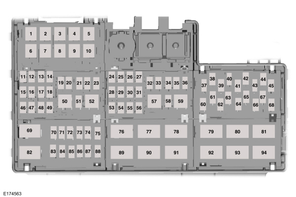
| Fuse or Relay Number | Fuse Rating | Protected Component |
|---|---|---|
| 1 | — | Not used. |
| 2 | — | Not used. |
| 3 | 30A1 | Electronic Fan 1. |
| 4 | 40A1 | Electronic Fan 3. |
| 5 | 50A1 | Automatic brake system pump. |
| 6 | 50A1 | Body control module. |
| 7 | 60A1 | Body control module. |
| 8 | 50A1 | Body control module. |
| 9 | 40A1 | Rear window defroster. |
| 10 | 40A1 | Blower motor. |
| 11 | 30A2 | Left-hand front window. |
| 12 | 30A2 | Driver seat. |
| 13 | 30A2 | Passenger seat. |
| 14 | 30A2 | Climate-controlled seat module. |
| 15 | 20A2 | Convertible top motor. |
| 16 | — | Not used. |
| 17 | 20A2 | Convertible top motor. |
| 18 | — | Not used. |
| 19 | 20A3 | Steering column lock relay. |
| 20 | 10A3 | Brake on-off switch. |
| 21 | 20A3 | Horn. |
| 22 | 10A3 | Powertrain control module relay. |
| 23 | 10A3 | Air conditioning clutch. |
| 24 | 30A2 | Voltage quality module. |
| 25 | — | Not used. |
| 26 | 25A2 | Windshield wiper motor. |
| 27 | — | Not used. |
| 28 | 30A2 | Automatic brake system valve. |
| 29 | — | Not used. |
| 30 | 30A2 | Starter motor solenoid. |
| 31 | — | Not used. |
| 32 | 10A3 | Latch relay coil. |
| 33 | 15A3 | Run/Start (except GT350). |
| 20A3 | Left-hand high-intensity discharge head-lamps (GT350 only). | |
| 34 | 15A3 | Exhaust valves. |
| 35 | 20A3 | Right-hand high-intensity discharge head-lamps (GT350 only). |
| 36 | 10A3 | Alt sense. |
| 37 | — | Not used. |
| 38 | 20A3 | Vehicle power 1. |
| 39 | — | Not used. |
| 40 | 20A3 | Vehicle power 2. |
| 41 | 15A3 | Fuel injectors (except 2.3L). |
| 42 | 15A3 | Vehicle power 3. |
| 43 | — | Not used. |
| 44 | 15A3 | Vehicle power 4. |
| 30A3 | Ignition coils (GT350 only). | |
| 45 | — | Not used. |
| 46 | 20A2 | Differential pump (Shelby). |
| 47 | — | Not used. |
| 48 | 30A2 | Fuel pump #2 (Shelby). |
| 49 | 30A2 | Fuel pump. |
| 50 | — | Steering column lock relay. |
| 51 | — | Not used. |
| 52 | — | Horn relay. |
| 53 | 20A2 | Cigar lighter. |
| 54 | 20A2 | Auxiliary power point. |
| 55 | 25A2 | Electronic fan 2. |
| 56 | — | Not used. |
| 57 | — | Air conditioning clutch relay. |
| 58 | — | Not used. |
| 59 | — | Exhaust valves relay. |
| 60 | 5A3 | Powertrain control module. |
| 61 | — | Not used. |
| 62 | 5A3 | Anti-lock brakes run-start switch. |
| 63 | — | Not used. |
| 64 | 5A3 | Electronic power assist steering. |
| 65 | — | Not used. |
| 66 | 5A3 | Blind spot information system. Rear view camera. Air conditioning compressor relay coils. Vehicle dynamics module. |
| 67 | — | Not used. |
| 68 | 10A3 | Headlamp leveling switch. |
| 69 | — | Auxiliary power point relay. |
| 70 | 10A3 | Heated exterior mirrors. |
| 71 | — | Not used. |
| 72 | 5A3 | Rain sensor module. |
| 73 | — | Not used. |
| 74 | 5A3 | Mass air flow sensor (except 2.3L). |
| 75 | — | Not used. |
| 76 | — | Rear window defroster relay. |
| 77 | — | Electronic cooling fan 2 relay. |
| 78 | — | Run/Start relay. |
| 79 | — | Not used. |
| 80 | — | Windshield wiper relay. |
| 81 | — | Starter motor solenoid relay. |
| 82 | — | Powertrain control module relay. |
| 83 | — | Not used. |
| 84 | — | Not used. |
| 85 | — | Not used. |
| 86 | — | Not used. |
| 87 | — | Not used. |
| 88 | — | Not used. |
| 89 | — | Electronic fan 1 relay. |
| 90 | — | Differential pump relay. |
| 91 | — | Electronic fan 3 relay. |
| 92 | — | Blower motor relay. |
| 93 | — | Fuel pump #2 relay. |
| 94 | — | Fuel pump relay. |
1J-case fuses.2M-case fuses.3Micro fuses.
Passenger Compartment Fuse Panel
The fuse panel is in the right-hand side of the passenger footwell behind a trim panel and plastic key code card.To remove the trim panel, lift it from the rear retaining hooks, while pulling it toward you and swinging it away from the side. To reinstall it, line up the tabs with the grooves on the panel, drop the panel back into place, and then push it shut.To reach the fuse panel, first remove the key code card.After replacing a fuse, return the key code card to the original position. To reinstall the trim panel, lineup the tabs with the grooves on the panel, drop the panel back into place, and then push it shut to reinstall the trim panel.
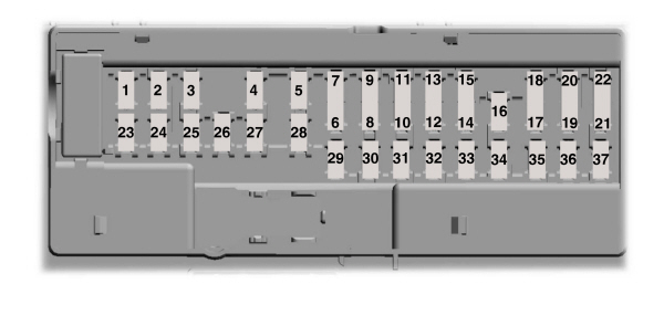
| Fuse or Relay Number | Fuse Rating | Protected Component |
|---|---|---|
| 1 | — | Not used. |
| 2 | 7.5A | Power mirror memory module (driver side mirror). Memory seat module. |
| 3 | 20A | Driver console unlock. |
| 4 | — | Not used. |
| 5 | 20A | Subwoofer amplifier. |
| 6 | — | Not used. |
| 7 | — | Not used. |
| 8 | — | Not used. |
| 9 | — | Not used. |
| 10 | 5A | Telematics. |
| 11 | — | Not used. |
| 12 | 7.5A | Climate control module. |
| 13 | 7.5A | Gateway module. Steering column control module. Instrument cluster. |
| 14 | 10A | Electronic power module. |
| 15 | 10A | Gateway module. |
| 16 | 15A | Decklid release. |
| 17 | 5A | Battery backed sounder. |
| 18 | 5A | Intrusion sensor module. |
| 19 | 7.5A | Electronic power module. |
| 20 | 7.5A | Headlamp control module. |
| 21 | 5A | In-vehicle temperature and humidity sensor. Front camera. |
| 22 | 5A | Not used (spare). |
| 23 | 10A | Switches. Power windows. Rear-view mirror. |
| 24 | 20A | Central lock/unlock. |
| 25 | 30A | Vehicle dynamics module. |
| 26 | 30A | Right-hand front-window motor (power distribution module). |
| 27 | 30A | Amplifier. |
| 28 | 20A | Auxiliary body module. |
| 29 | 30A | Left-hand rear-window power. |
| 30 | 30A | Right-hand rear-window power. |
| 31 | — | Not used. |
| 32 | 10A | Remote keyless entry. Multi-function display. SYNC. Global positioning system module. Gauges. |
| 33 | 20A | Audio head unit. |
| 34 | 30A | Run-start bus. |
| 35 | 5A | Not used (spare). |
| 36 | 15A | Auxiliary body module. |
| 37 | 20A | Heated steering wheel module. |
CHANGING A FUSE
Fuses
| WARNING: Always replace a fuse with one that has the specified amperage rating. Using a fuse with a higher amperage rating can cause severe wire damage and could start a fire. |

If electrical components in the vehicle are not working, a fuse may have blown. Blown fuses are identified by a broken wire within the fuse. Check the appropriate fuses before replacing any electrical components.
Fuse Types
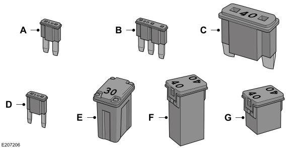
| Callout | Fuse Type |
|---|---|
| A | Micro 2 |
| B | Micro 3 |
| C | Maxi |
| D | Mini |
| E | M Case |
| F | J Case |
| G | J Case Low Profile |
To download the complete user manual, please download the following file: