
FUSE SPECIFICATION CHART
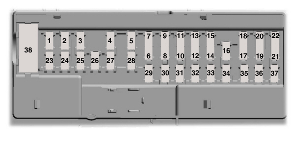
Power Distribution Box
 WARNING: Always disconnect the battery before servicing high current fuses. WARNING: To reduce risk of electrical shock, always replace the cover to the power distribution box before reconnecting the battery or refilling fluid reservoirs. WARNING: Always disconnect the battery before servicing high current fuses. WARNING: To reduce risk of electrical shock, always replace the cover to the power distribution box before reconnecting the battery or refilling fluid reservoirs. |
The power distribution box is in the engine compartment. It has high-current fuses that protect your vehicle’s main electrical systems from overloads.Some features need to be reset when you or someone else disconnects and reconnects the battery. See Changing the 12V Battery.

| Fuse or Relay Number | Fuse Rating | Protected Component |
|---|---|---|
| 1 | 30A1 | Panoramic moonroof. |
| 2 | – | Starter relay. |
| 3 | 15A3 | Rain sensor. |
| 4 | — | Blower motor relay. |
| 5 | 20A 1 | Power point 3 – back of console. |
| 6 | — | Not used. |
| 7 | 20A 3 | Powertrain control module – vehicle power 1. Powertrain control module power. |
| 8 | 20A 3 | Powertrain control module – vehicle power 2. Emission components. |
| 9 | — | Powertrain control module relay. |
| 10 | 20A 1 | Power point 1 – driver front. |
| 11 | 15A 2 | Powertrain control module – vehicle power 4. Ignition coils. |
| 12 | 15A 2 | Powertrain control module – vehicle power 3. Non-emission components. |
| 13 | 10A 2 | Not used (spare). |
| 14 | 10A 2 | Not used (spare). |
| 15 | — | Run-start relay. |
| 16 | 20A 1 | Power point 2 – console. |
| 17 | 20A 1 | Not used (spare). |
| 18 | 20A 3 | Not used (spare). |
| 19 | 10A 3 | Run-start electronic power assist steering. |
| 20 | 10A 3 | Adaptive cruise control. |
| 21 | 15A 3 | Run/start transmission control. Transmission oil pump start/stop. |
| 22 | 10A 3 | Air conditioner clutch solenoid. |
| 23 | 15A 3 | Run-start. Blind spot information system. Rear view camera. Heads-up display. Voltage stability module. Gear shift actuator. |
| 24 | — | Not used. |
| 25 | 10A 2 | Run-start anti-lock brake system. |
| 26 | 10A 2 | Run-start powertrain control module. |
| 27 | 10A3 | Not used (spare). |
| 28 | — | Not used. |
| 29 | 5A 3 | Mass air flow monitor. |
| 30 | — | Not used. |
| 31 | — | Not used. |
| 32 | — | Electric fan 1 relay. |
| 33 | — | A/C clutch relay. |
| 34 | — | Not used. |
| 35 | — | Not used. |
| 36 | — | Not used. |
| 37 | — | Not used. |
| 38 | — | Electric fan 2 relay. |
| 39 | — | Electric fan coil 2 and 3 relay. |
| 40 | — | Horn relay. |
| 41 | — | Not used. |
| 42 | — | Fuel pump coil relay. |
| 43 | — | Not used. |
| 44 | 20A 3 | Left hand side headlamp ballast. |
| 45 | 5A 3 | Not used (spare). |
| 46 | — | Not used. |
| 47 | — | Not used. |
| 48 | — | Not used. |
| 49 | 10A 3 | Not used (spare). |
| 50 | 20A 3 | Horn. |
| 51 | — | Not used. |
| 52 | — | Not used. |
| 53 | 10A 3 | Not used (spare). |
| 54 | 10A 2 | Brake on off switch. |
| 55 | 10A 2 | ALT sensor. |
1Micro 2 fuse.2Micro 3 fuse.3M case fuse.
Power Distribution Box – Bottom
There are fuses on the bottom of the fuse box. To access the bottom of the fuse box, do the following:

- Release the two latches on both sides of the fuse box.
- Raise the inboard side of the fuse box from the cradle.
- Move the fuse box toward the center of the engine compartment.
- Pivot the outboard side of the fuse box to access the bottom side.
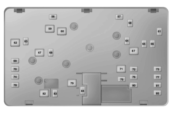
| Fuse or Relay Number | Fuse Rating | Protected Component |
|---|---|---|
| 56 | — | Not used. |
| 57 | — | Not used. |
| 58 | 30A 4 | Fuel pump feed. |
| 59 | 30A 5 | Electric fan 3 |
| 60 | 30A 5 | Electric fan 1 (1.5L, 2.0L, and 2.5L engines). |
| 61 | — | Not used. |
| 62 | 50A 5 | Body control module 1. |
| 63 | 25A 4 | Electric fan 2 (1.5L, 2.0L, and 2.5L engines). |
| 64 | 30A 4 | Not used (spare). |
| 65 | 20A 4 | Front heated seat. |
| 66 | 15A 4 | Not used (spare). |
| 67 | 50A 5 | Body control module 2. |
| 68 | 40A 4 | Heated rear window. |
| 69 | 30A 4 | Anti-lock brake system valves. |
| 70 | 30A 4 | Passenger seat. |
| 71 | — | Not used. |
| 72 | 20A 4 | Trans oil pump. |
| 73 | 20A 4 | Rear heated seats. |
| 74 | 30A 4 | Driver seat module. |
| 75 | 25A 4 | Wiper motor 1. |
| 76 | 30A 4 | Not used (spare). |
| 77 | 30A 4 | Climate control seat module. |
| 78 | — | Not used. |
| 79 | 40A 5 | Blower motor. |
| 80 | 25A 4 | Wiper motor 2. |
| 81 | 40A 4 | Inverter. |
| 82 | – | Not used. |
| 83 | 20A 4 | TRCM shifter. |
| 84 | 30A 4 | Starter solenoid. |
| 85 | 30A 4 | Not used (spare). |
| 86 | 30A 4 | Not used (spare). |
| 87 | 60A 5 | Anti-lock brake system pump. |
4M case fuse.5J case fuse.
Passenger Compartment Fuse Panel
The fuse panel is under the instrument panel to the left of the steering column.
Note: It may be easier to access the fuse panel if you remove the finish trim piece.
| Fuse or Relay Number | Fuse Rating | Protected Component |
|---|---|---|
| 1 | – | Not Used |
| 2 | 7.5A 6 | Lumbar. |
| 3 | 20A 6 | Driver door unlock. |
| 4 | 5A 6 | Not used (spare). |
| 5 | 20A 6 | Subwoofer amplifier. |
| 6 | 10A 7 | Not Used (spare). |
| 7 | 10A 7 | Not used (spare). |
| 8 | 10A 7 | Not used (spare). |
| 9 | 10A 7 | Not used (spare). |
| 10 | 5A 7 | Keypad. Cellphone passport module. |
| 11 | 5A 7 | Not used (spare). |
| 12 | 7.5A 7 | Climate control. Gear shift |
| 13 | 7.5A 7 | Steering wheel column lock. Cluster. Datalink logic. |
| 14 | 10A 7 | Extended power module. |
| 15 | 10A 7 | Datalink gateway module. |
| 16 | 15A 6 | Child lock. |
| 17 | 5A 7 | Not used (spare). |
| 18 | 5A 7 | Push button stop start switch. |
| 19 | 7.5A 7 | Extended power module. |
| 20 | 7.5A 7 | Adaptive headlamp. |
| 21 | 5A 7 | Humidity and in–car temperature sensor. |
| 22 | 5A 7 | Not used (spare). |
| 23 | 10A 6 | Delayed accessory (power inverter logic, moonroof logic, driver master switch). |
| 24 | 20A 6 | Central lock/unlock. |
| 25 | 30A 6 | Driver door (window, mirror). |
| 26 | 30A 6 | Front passenger door (window, mirror). |
| 27 | 30A 6 | Moonroof. |
| 28 | 20A 6 | Amplifier. |
| 29 | 30A 6 | Rear driver side door (window). |
| 30 | 30A 6 | Rear passenger side door (window). |
| 31 | 15A 6 | Not used (spare). |
| 32 | 10A 6 | Global positioning system. Display. Voice control. Radio frequency receiver. |
| 33 | 20A 6 | Radio. Active noise control. |
| 34 | 30A 6 | Run-start bus (fuse 19, 20, 21, 22, 35, 36, 37, circuit breaker). |
| 35 | 5A 6 | Not used (spare). |
| 36 | 15A 6 | Auto-dimming rear view mirror. Continuous control damping suspension. Rear heated seats. |
| 37 | 20A 6 | Heated steering wheel. |
| 38 | 30A | Not used. |
6Micro 2 fuse.
7Micro 3 fuse.
CHANGING A FUSE
Fuses
| WARNING: Always replace a fuse with one that has the specified amperage rating. Using a fuse with a higher amperage rating can cause severe wire damage and could start a fire. |

If electrical components in the vehicle are not working, a fuse may have blown. Blown fuses are identified by a broken wire within the fuse. Check the appropriate fuses before replacing any electrical components.
Fuse Types
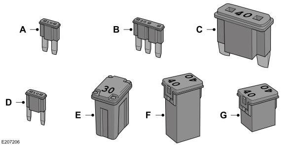
| Callout | Fuse Type |
|---|---|
| A | Micro 2 |
| B | Micro 3 |
| C | Maxi |
| D | Mini |
| E | M Case |
| F | J Case |
| G | J Case Low Profile |
To download the complete user manual, please download the following file: