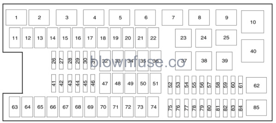
Power Distribution Box
 WARNING: Always disconnect the battery before servicing high current fuses. WARNING: To reduce risk of electrical shock, always replace the cover to the power distribution box before reconnecting the battery or refilling fluid reservoirs. WARNING: Always disconnect the battery before servicing high current fuses. WARNING: To reduce risk of electrical shock, always replace the cover to the power distribution box before reconnecting the battery or refilling fluid reservoirs. |
The power distribution box is located in the engine compartment. It has high-current fuses that protect your vehicle’s main electrical systems from overloads.If you disconnect and reconnect the battery, you will need to reset some features.
| Fuse or relay number | Fuse amp rating | Protected components |
|---|---|---|
| 1 | Relay | Powertrain control module (3.7L, 5.0L and 6.2L engines) |
| 2 | Relay | Starter |
| 3 | Relay | Blower motor |
| 4 | Relay | Rear window defroster |
| 5 | Relay | Electric fan (high speed) |
| 6 | Relay | Trailer tow park lamp |
| 7 | Relay | Run/start |
| 8 | Relay | Fuel pump |
| 9 | Relay | Trailer tow battery charger |
| 10 | Relay | Powertrain control module (3.5L engine) |
| 11 | 30A* | Power running board motors |
| 12 | 40A* | Electric fan (3.7L, 5.0L) |
| 50A* | Electric fan (3.5L, 6.2L with max trailer tow, SVT Raptor) | |
| 13 | 30A* | Starter relay power |
| 14 | 30A* | Passenger power seat |
| 15 | 40A* | Electric fan (3.7L, 5.0L) |
| 50A* | Electric fan (3.5L, 6.2L with max trailer tow, SVT Raptor) | |
| 16 | 20A* | High-intensity discharge headlamp – passenger side |
| 17 | 30A* | Trailer brake control |
| 18 | 30A* | Auxiliary switch 1 (SVT Raptor) |
| 19 | 30A* | Auxiliary switch 2 (SVT Raptor) |
| 20 | 20A* | 4×4 module (electronic shift) |
| 21 | 30A* | Trailer tow battery charge relay power |
| 22 | 20A* | Auxiliary power point (instrument panel) |
| 23 | Relay | Air conditioner clutch |
| 24 | — | Not used |
| 25 | — | Not used |
| 26 | 10A** | Powertrain control module – keep alive power and relay coil, canister vent solenoid (3.7L, 5.0L and 6.2L engines) |
| 27 | 20A** | Fuel pump relay power |
| 28 | 10A** | Auxiliary switch 4 (SVT Raptor) |
| 29 | 10A** | 4×4 integrated wheel end solenoid |
| 30 | 10A** | Air conditioner clutch relay power |
| 31 | 15A** | Run/start relay power |
| 32 | 40A* | Rear window defroster relay power, Heated mirror relay power |
| 33 | 40A* | 110-volt AC power point |
| 34 | 40A* | Powertrain control module relay power (3.7L, 5.0L and 6.2L engines) |
| 50A* | Powertrain control module relay power (3.5L engine) | |
| 35 | 20A* | High-intensity discharge headlamps – driver side |
| 36 | 30A* | Roll stability control / Anti-lock brake system |
| 37 | Relay | Trailer tow left stop/turn |
| 38 | Relay | Trailer tow right stop/turn |
| 39 | Relay | Trailer tow back-up lamps |
| 40 | Relay | Electric fan |
| 41 | 15A** | Front camera washer (SVT Raptor) |
| 42 | 5A** | Run/start relay coil |
| 43 | 15A** | Trailer tow back-up lamp relay power |
| 44 | 15A** | Auxiliary switch 3 (SVT Raptor), Trailer tow power folding mirrors |
| 45 | 10A** | Alternator sensor (3.5L, 3.7L and 5.0L engines) |
| 46 | 10A** | Brake on/off switch |
| 47 | 60A* | Roll stability control / Anti-lock brake system module |
| 48 | 20A* | Moonroof |
| 49 | 30A* | Wiper relay power |
| 50 | — | Not used |
| 51 | 40A* | Blower motor relay power |
| 52 | 5A** | Run/start – Electronic power assist steering, Blower relay coil |
| 53 | 5A** | Run/start – Powertrain control module |
| 54 | 5A** | Run/start – 4×4 module, Back-up lamps, Roll stability control /Anti-lock brake system, Trailer tow battery charge relay coil, Rear window defroster relay coil, Front camera washer relay coil (SVT Raptor) |
| 55 | — | Not used |
| 56 | 15A** | Heated mirrors |
| 57 | — | Not used |
| 58 | — | Not used |
| 59 | — | Not used |
| 60 | — | Not used |
| 61 | — | Not used |
| 62 | Relay | Wiper motor |
| 63 | 25A* | Electric fan relay power |
| 64 | — | Not used |
| 65 | 20A* | Auxiliary power point (instrument panel) |
| 66 | 20A* | Auxiliary power point (inside center console) |
| 67 | 20A* | Trailer tow park lamps relay power |
| 68 | 25A* | 4×4 module, 4×2 elocker module |
| 69 | 30A* | Front heated or heated/cooled seats |
| 70 | — | Not used |
| 71 | 20A* | Heated rear seats |
| 72 | 20A* | Auxiliary power point (rear) |
| 73 | 20A* | Trailer tow stop/turn lamps relay power |
| 74 | 30A* | Driver power seat/memory module |
| 75 | 15A** | Powertrain control module – voltage power 1 (3.7L, 5.0L, 6.2L engines) |
| 25A** | Powertrain control module – voltage power 1 (3.5L engine) | |
| 76 | 20A** | Powertrain control module – Voltage power 2: General powertrain components (Mass air flow/Intake air temp sensor – 3.7L, 5.0L, 6.2L engines) (Canister vent solenoid – 3.5L engine) |
| 77 | 10A** | Powertrain control module – Voltage power 3 (Emission related powertrain components, Electric fan relays coil) |
| 78 | 15A** | Powertrain control module – Voltage power 4 – Ignition coils (3.5L, 3.7L, 5.0L engines) |
| 20A** | Powertrain control module – Voltage power 4 – Ignition coils (6.2L engine) | |
| 79 | 5A** | Rain sensor |
| 80 | — | Not used |
| 81 | — | Not used |
| 82 | — | Not used |
| 83 | — | Not used |
| 84 | — | Not used |
| 85 | Relay | Electric fan (low speed) |
*Cartridge fuses**Mini fuses
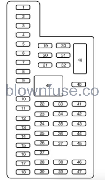
Passenger Compartment Fuse Panel
The fuse panel is in the right-hand side of the passenger footwell behind a trim panel.To remove the trim panel, pull it toward you and swing it away from the side. To reinstall it, line up the tabs with the grooves on the panel, and then push it shut.To remove the fuse panel cover, press in the tabs on both sides of the cover, and then pull it off.To reinstall the fuse panel cover, place the top part of the cover on the fuse panel and push the bottom part until it latches. Gently pull on the cover to make sure it has latched properly.
| Fuse or relay number | Fuse amp rating | Protected components |
|---|---|---|
| 1 | 30A | Driver side front window |
| 2 | 15A | SYNC , Display module (8 inch) |
| 3 | 30A | Passenger side front window |
| 4 | 10A | Interior lamps |
| 5 | 20A | Memory module |
| 6 | 5A | Not used (spare) |
| 7 | 7.5A | Power mirror switch, Memory seat module |
| 8 | 10A | Not used (spare) |
| 9 | 10A | Radio display, GPS module, Electric finish panel module |
| 10 | 10A | Run/accessory relay |
| 11 | 10A | Instrument cluster |
| 12 | 15A | Interior lighting, Puddle lamps, Backlighting, Cargo lamp |
| 13 | 15A | Right turn signals/stop lamps |
| 14 | 15A | Left turn signals/stop lamps |
| 15 | 15A | Reverse lights, High-mounted stop lamp |
| 16 | 10A | Right low-beam headlamp |
| 17 | 10A | Left low-beam headlamp |
| 18 | 10A | Brake-shift interlock, Keypad illumination, Powertrain control module wake-up, Passive anti-theft system |
| 19 | 20A | Audio amplifier |
| 20 | 20A | Power door locks |
| 21 | 10A | Not used (spare) |
| 22 | 20A | Horn |
| 23 | 15A | Steering wheel control module |
| 24 | 15A | Datalink connector, Steering wheel control module |
| 25 | 15A | Not used (spare) |
| 26 | 5A | Radio frequency module |
| 27 | 20A | Not used (spare) |
| 28 | 15A | Ignition switch |
| 29 | 20A | Radio |
| 30 | 15A | Front parking lamps |
| 31 | 5A | Brake on/off – Instrument panel, Engine |
| 32 | 15A | Delay/accessory – moonroof, power windows, locks, Automatic dimming mirror/Compass, Trailer tow power telescope mirrors |
| 33 | 10A | Rear heated seats |
| 34 | 10A | Reverse sensing system, 4×4 switch, Rear video, Off-road indicator (SVT Raptor), Front video (SVT Raptor), Camera splice module (SVT Raptor) |
| 35 | 5A | Hill descent switch (SVT Raptor) |
| 36 | 10A | Restraint control module, Occupant classification system module |
| 37 | 10A | Trailer brake control |
| 38 | 10A | Delayed accessory – 110-volt power point, Radio |
| 39 | 15A | High-beam headlamps |
| 40 | 10A | Rear park lamps |
| 41 | 7.5A | Passenger airbag deactivation indicator, Auxiliary switch (SVT Raptor) |
| 42 | 5A | Overdrive cancel switch |
| 43 | 10A | Not used (spare) |
| 44 | 10A | Not used (spare) |
| 45 | 5A | Not used (spare) |
| 46 | 10A | Climate controls module |
| 47 | 15A | Fog lamps, Exterior mirror turn signals |
| 48 | 30A Circuit breaker | Power windows, Power sliding back window |
| 49 | Relay | Delayed accessory |
Auxiliary relay box (SVT Raptor only)
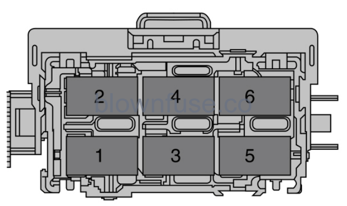
The relay box is located in the left-hand corner of the engine compartment near the windshield.
| Fuse or relay number | Fuse amp rating | Protected components |
|---|---|---|
| 1 | Relay | Auxiliary switch 1 |
| 2 | Relay | Auxiliary switch 2 |
| 3 | Relay | Auxiliary switch 3 |
| 4 | Relay | Auxiliary switch 4 |
| 5 | Relay | Front camera washer |
| 6 | — | Not used |
2014 Ford F-150 Owners Manual
Information regarding mileage, safety, and performance.
Changing a Fuse
| WARNING: Always replace a fuse with one that has the specified amperage rating. Using a fuse with a higher amperage rating can cause severe wire damage and could start a fire. |

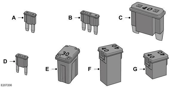
| Callout | Fuse Type |
|---|---|
| A | Micro 2 |
| B | Micro 3 |
| C | Maxi |
| D | Mini |
| E | M Case |
| F | J Case |
| G | J Case Low Profile |