2022 XC90 Volvo Loading
Recommendations for loading
- There are a number of things that are important to bear in mind when loading the car.
- Payload depends on the car’s curb weight.
- The total weight of the passengers and all accessories reduces the car’s payload by a corresponding weight.
Warning
The car’s driving properties change depending on the weight and positioning of the load.
Loading in the cargo area
Good things to remember when loading:
- Position the load firmly against the rear seat’s backrest.
- Heavy objects should be placed as low as possible. Avoid placing heavy loads on lowered backrests.
- Cover sharp edges with something soft to avoid damaging the upholstery.
- Secure all loads to the load-retaining eyelets with straps or web lashings.
Warning
A loose object weighing 20 kg (44 pounds) can, in a frontal collision at a speed of 50 km/h (30 mph) carry the impact of an item weighing 1000 kg (2200 pounds).
Warning
Leave 10 cm (4 inches) space between the load and the side windows if the car is loaded above the top edge of the door windows. Otherwise, the intended protection of the inflatable curtain, which is concealed in the headlining, may be compromised.
Warning
- Always secure the load. During heavy braking the load may otherwise shift, causing injury to the car’s occupants.
- Cover sharp edges and sharp corners with something soft.
- Switch off the engine and apply the parking brake when loading/unloading long items.
- Otherwise, you may accidentally knock the gear lever or gear selector with the load into a drive position – and the car could then move off.
Increasing the space in the cargo area
Level control of the car’s rear section
Level control is performed via control at the rear on the right-hand side in the cargo area’s side panel.
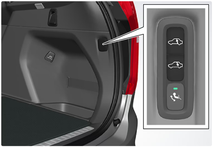
- Controls for raising/lowering the car’s rear section.
- The control consists of two buttons – one button that lowers and one button that raises the rear section of the car.
- For raising or lowering, each button must be held depressed until the rear section has reached the desired level.
- It is not possible to raise the car’s rear section higher than its normal level.
- During driving, the rear section height will return to the normal level.
Note
It is not possible to adjust the height of the rear section when one or more of the doors or the bonnet is open. This does not apply to the tailgate.
Warning
Pay attention to ensure that there is no person, animal, or object under the car when lowering. This would involve danger to life and damage to the car or object.
Bag hooks
Along the sides
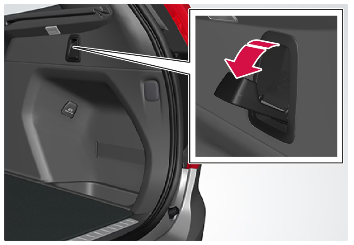 There are two extensible bag hooks in the side panels – one on each side of the cargo area.
Important
The bag hooks may be loaded with a maximum of 5 kg (11 lbs).
Under the floor hatch
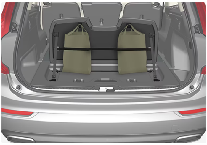 There are two bag hooks and an elastic strap in the cover, which is part of the floor hatch in the cargo area.
- The strap can be fitted in four different positions.
- Lift up the cover in order to use the bag hooks.
- Fasten the bags in a suitable position with the enclosed elastic strap.
- If the bags have handles and are a suitable height – hang them in the hooks.
Operating cargo cover
Full-cover position
For 7-seat car
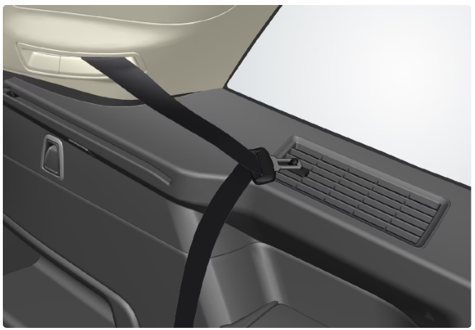 Hang up the locking tabs of the seatbelts for the third seat row on the designated hooks in the side panels.
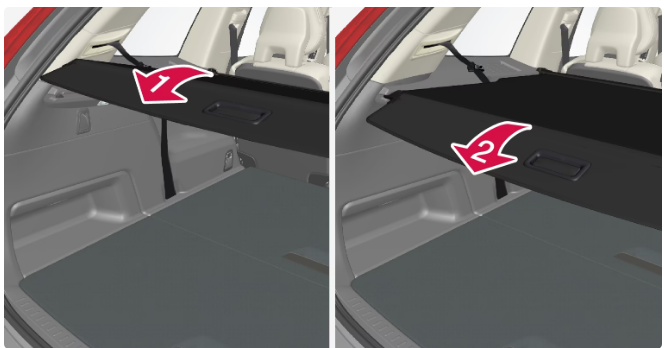 Grip the handle and pull out the cargo cover so that it slides over the side panels in the cargo area. Pull to the end position.
- When the cargo cover is extended so that it covers the cargo area – guide the cover’s attachment pins into the grooves in the side panels and release, while at the same time angling the handle with a light downward pressure.
- The cargo cover is locked in the full-cover position.
For 5-seat car
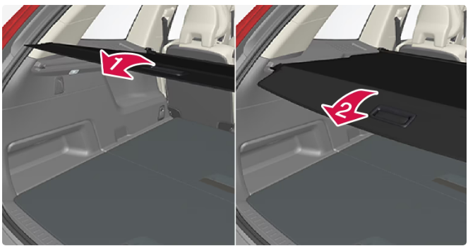 Grip the handle and pull out the cargo cover so that it slides over the side panels in the cargo area. Pull to the end position.
- When the cargo cover is extended so that it covers the cargo area – guide the cover’s attachment pins into the grooves in the side panels and release, while at the same time angling the handle with a light downward pressure.
- The cargo cover is locked in the full-cover position.
Important
Do not load objects on top of the cargo cover.
Warning
In a 7-seat car, never have the cargo cover fitted when there are passengers in the rear seats. This may lead to serious injury in the event of a collision.
Loading mode
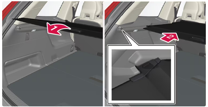 From the retracted position – grip the handle and pull out the cover so it slides over the side panels in the cargo area – pull to the end position and guide the cargo cover’s attachment pins into the grooves in the side panels. (If the cover is already in the full-cover position – see the next point)
- From the full-cover position – grip the handle and guide the cargo cover’s attachment pins into the grooves in the side panels and release.
- Retract the cover until it stops in the loading position.
- In the event that your hands are occupied:
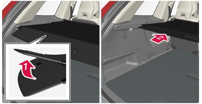 In the extended full-cover position – lightly push the handle part of the cargo cover upward, e.g. with an elbow.
- The cover retracts until it stops in the loading position.
- To return to the full-cover position from the loading position:
- Grip the handle and pull the cargo cover out to the end position.
- Release slightly and angle the handle by means of a light downward pressure.
- The cover is locked in the full-cover position.
Retracting
- From the full-cover position:
- Lift up the handle and pull it back to disengage the cargo cover’s attachment pins and then release.
- From loading position:
- Grip the handle and pull out the cargo cover in the grooves – pull to the full-cover position. Lift up the handle and pull it back to disengage the attachment pins and then release.
- Retract the cover with its attachment pins outside of the side panels until it stops in the retracted position.
Fitting and removing cargo cover
Fitting cargo cover
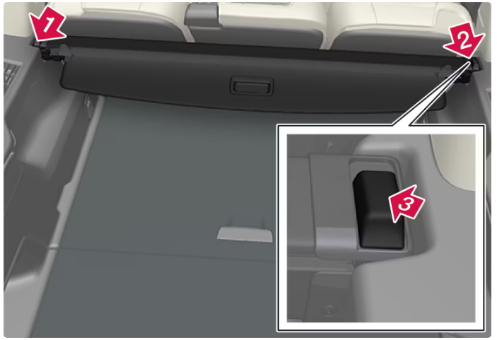 Insert one of the cargo cover’s end pieces in the recess in the side panel in the cargo area.
- Then insert the other end piece in the recess in the side panel on the opposite side.
- Press down the end pieces on both sides – one by one.
- When a “click” is heard and the red marking on each end piece has disappeared, the cargo cover is attached – check that it is affixed securely.
Removing cargo cover
- In retracted position:
- Depress the button on one of the retracted cargo cover’s end pieces and lift out that end.
- In a 7-seat car – release the third seat row’s seatbelt locking tabs from the hooks above the side panels.
- Angle the cover-up/out carefully.
- The other end piece loosens automatically and the cover can be lifted out of the cargo area.
Load retaining eyelets
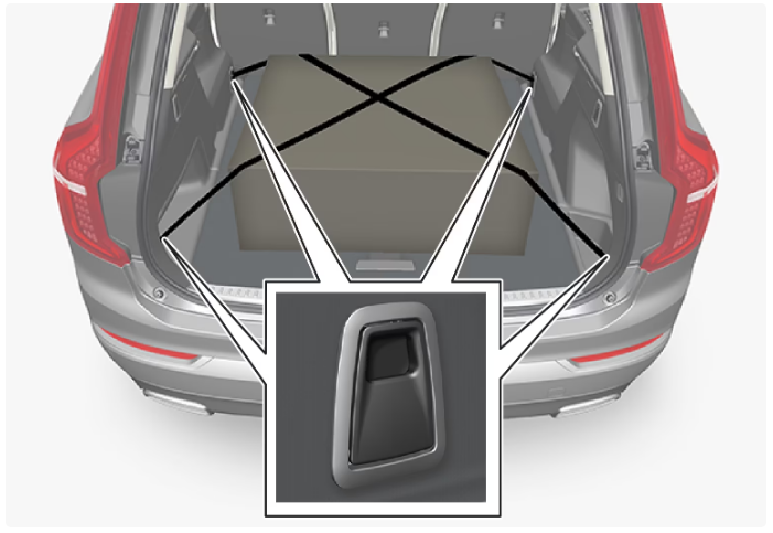
Hard, sharp, and heavy objects that are loose or protrude may cause injury during heavy braking.
Always secure large and heavy objects with a seatbelt or cargo retaining straps.
Fitting and removing safety grilles
The safety grille is crash-tested in accordance with the ECE R17 legal requirement and fulfills Volvo’s strength requirements.
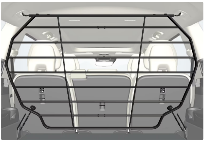 For safety reasons, the safety grille must always be attached and anchored correctly.
Under no circumstances may anybody remain in the cargo area while the car is moving. This is to avoid injury in the event of heavy braking or an accident.
The safety grille’s parts consist of the grille and two loose attaching braces. The attaching braces each come with a screw cap and there are two plastic sleeves for the safety grille.
Warning
The safety grille must only be used in the rear position described here. The roof mountings behind the front seats are not intended for the safety grille.
Warning
For safety reasons, the third seat row must be lowered when the safety grille is fitted into the car.
Important
It is not possible to have the protective grille fitted at the same time as the cargo cover.
Installation
Lower the rear seat and then lift the safety grille in through one of the rear side doors or via the tailgate – the arched/convex side of the grille should face the cargo area while the hooks on each side point up. The attaching braces and plastic sleeves are not used in this stage.
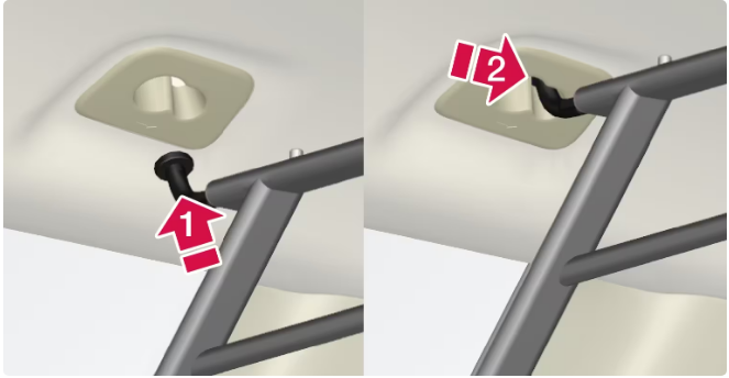 Guide one of the safety grille’s hooks into the larger opening in the roof mounting (1).
- Grasp the grille near the hook and pull/slide it towards the smaller opening (2).
- The hook is now secured in the roof mounting’s end position.
- Repeat the steps in point 2 above to secure the other hook in the mounting on the other side.
Make sure the hooks of the safety grille are securely fitted in the roof mountings so there is no risk of the grille coming loose.
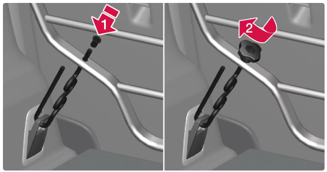 Hook the attaching brace’s hook through the load-securing eyelet at the cargo floor from underneath, and guide the threaded part through the cargo grille’s lower attachment hole from underneath (1).
- Slide a plastic sleeve on the threaded part of the attaching brace – the sleeve flange should face up – and guide it down through the hole. Then screw on the screw cap until its lower edge is approx. 5 mm from the grille (2).
- Repeat the steps in point 4 on the other side.
- Center the safety grille and then tighten the two attaching braces alternately until the grille is properly secured.
Removal
- Remove the safety grille by performing the above steps in reverse order.
- Note that the attaching braces can be removed before the plastic sleeves are removed from the holes in the grille.
Fitting and removing the safety net
The safety net is fitted into four mounting points.
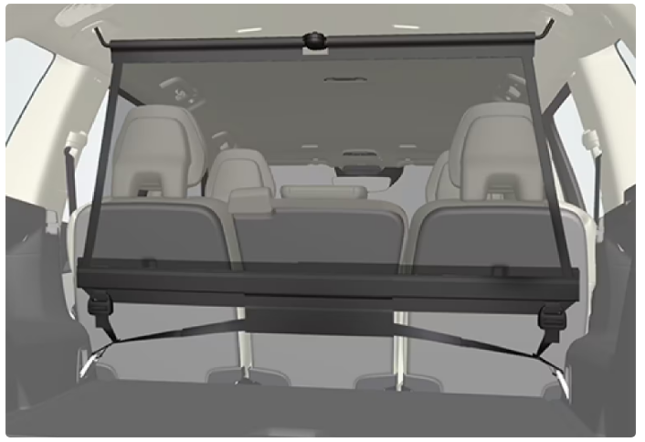 For reasons of safety, the safety net must always be fastened and anchored as described below.
The net is made of strong nylon fabric and can be secured in two different locations in the car:
- Rear fitting – behind second seat row.
- Front fitting – behind the front seats.
WarningLoads in the luggage compartment must be anchored well and also use a correctly fitted safety net.
Fitting the safety net
Check that the safety net’s upper mountings are correctly fitted and that the puller straps are securely hooked on.
Damaged safety nets must not be used.
With forward mounting, the safety net is most easily mounted via the rear doors.
Unfold the safety net and make sure that the split upper rod in the net is locked in its extended position.
Hook one retaining hook of the net into the front or rear roof mounting with the anchoring strap locks turned towards you.
Hook the net’s second attachment hook to the roof bracket on the opposite side.
The telescopically sprung attachment hooks make it easier to fit.
Take care to press forward the net’s retaining hooks for each respective roof mounting’s front-end position.
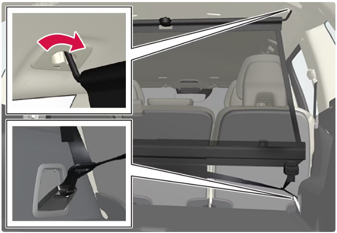 Rear fitting.
- For rear fitting:
- With the net fitted in the rear roof mountings, hook the safety net’s puller straps into the front load retaining eyelets in the cargo area.
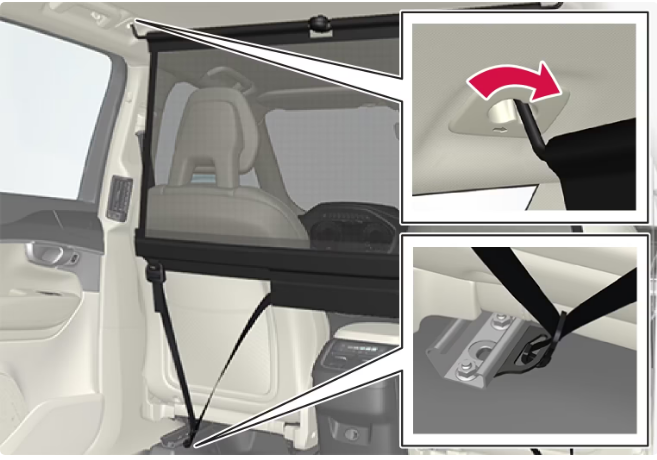 Front fitting.
- For front fitting:
- With the net fitted in the front roof mountings, hook the puller straps into the outer eyes on the rear of all seat slide rails.
- The procedure is facilitated if the backrests are straightened and the seats are moved forward slightly.
- Pay attention to make sure that you do not exert hard pressure on the net when the seat and backrest are moved back again.
- Only adjust until the seat or backrest makes contact with the net.
If a seat or backrest is pushed back hard into the safety net, the net and roof mounts may be damaged.
Tension the safety net with the anchoring straps.
Removing the safety net
- The safety net can be easily removed and folded up.
- Reduce safety net tension by pressing the button in the anchoring strap lock and feeding out a little of the anchoring strap on each side.
- Press in the catches and detach both of the anchoring strap’s hooks.
- Undo the upper attachments and release the net from the roof mountings.
- Press the red button on the rod to enable folding and then roll up the net. Store the net in its case.
Passenger compartment interior
Front seat
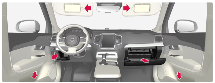 Storage compartment in the door panel and by the steering wheel, glovebox, and sun visors.
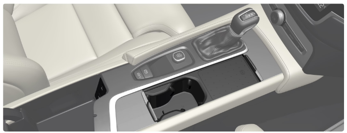 Storage spaces with cup holder, wireless phone charger, electrical socket, as well as USB ports in the tunnel console.
Second seat row
In cars with six seats
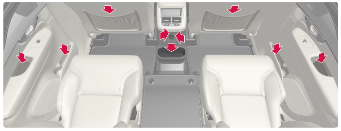 Storage compartment in the door panel, cup holder on the tunnel console’s floor, in the center seat backrest, storage pocket on the front seat backrest, as well as USB ports in the tunnel console.
In cars with seven seats
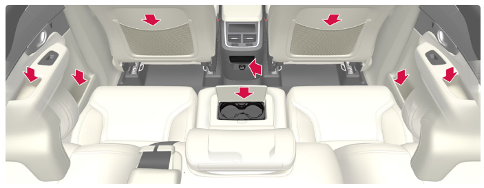 Storage compartment in the door panel, cup holder in the center seat backrest, storage pocket on the front seat backrest, as well as USB ports in the tunnel console.
Third seat row
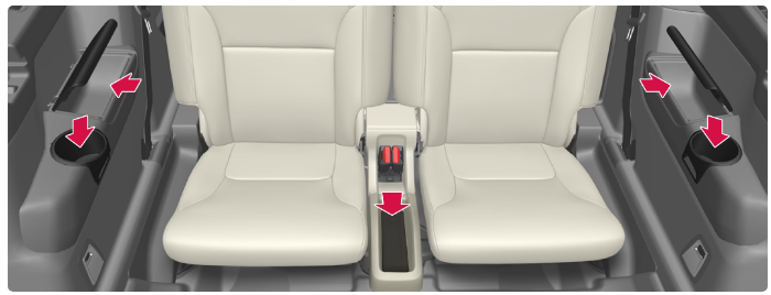 Storage compartment and a cup holder in the side panel and storage space between the seats.
Keep loose objects such as phones, cameras, remote controls for accessories, etc. in the glove compartment or other compartments. Otherwise, they may injure people in the car in the event of sudden braking or a collision.
Keep in mind that high gloss surfaces, for example, are easily scratched by metal objects. Do not place keys, phones, and other items on sensitive surfaces.
Electrical sockets
If a problem occurs with an electrical socket, contact a workshop – an authorized Volvo workshop is recommended.
12 V electrical socket
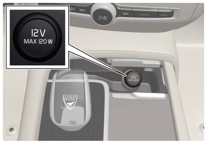 The tunnel console’s front electrical socket for cars with a wireless phone charger.
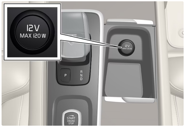 The tunnel console’s front electrical socket for cars without a wireless phone charger.
- The 12 V sockets can be used for various accessories designed for this, such as music players, cooler boxes, and mobile phones.
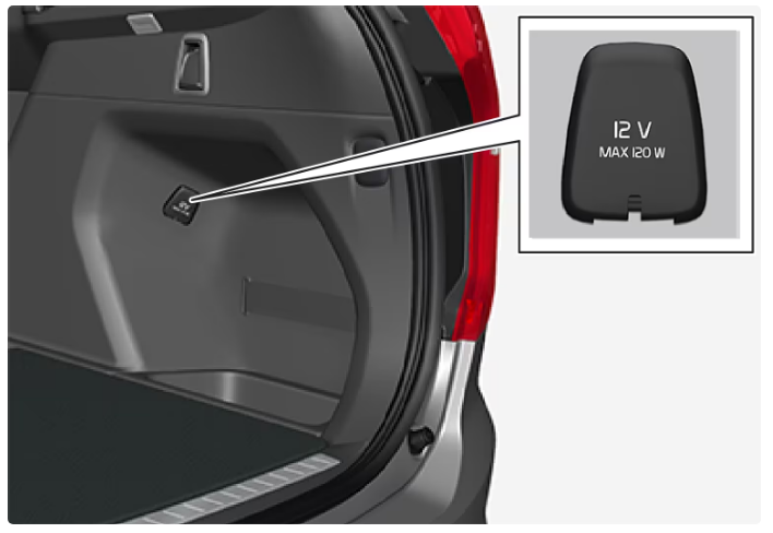 12 V electrical socket in the cargo area.
Using electrical sockets
For the sockets to supply current, the car’s electrical system must be set in the lowest ignition position I. The sockets are then active as long as the starter battery level does not become too low.
If the engine is switched off and the car is locked, the sockets are deactivated. If the engine is switched off and the car is not locked or is locked with a double lock temporarily deactivated, then the sockets continue to be active for a further seven minutes.
Remember that the use of the electrical socket with the engine switched off entails a risk of discharging the starter battery, which can limit functionality. Accessories that are connected to the electrical sockets may be activated even when the car’s electrical system is disconnected or if preconditioning is used. For this reason, disconnect the connectors when they are not in use in order to avoid the starter battery being discharged.
Warning
- Do not use accessories with large or heavy connectors – they can damage the socket or come loose when driving.
- Do not use accessories that can cause interference to the car’s radio receiver or electrical system for example.
- Position the accessory so that it is not at risk of injuring the driver or passengers in the event of heavy braking or collision.
- Keep an eye on connected accessories as they can generate heat that can burn passengers or the interior.
Using 12 V sockets
Remove the blanking plug (tunnel console) or fold down the cover (cargo area) in front of the socket and plug in the accessory’s connector.
Unplug the accessory’s connector and refit the blanking plug (tunnel console) or fold up the cover (cargo area) when the socket is not in use or if the socket is left unattended.
Maximum socket output is 120 W (10 A) per socket.
Using the glovebox
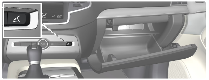
The glove box is opened by pressing the opening button in the center console.
Locking and unlocking the glovebox
The glove box can be locked, so-called private locking, e.g. when the car is taken in for service, left at a hotel, or similar. Private locking also locks the tailgate.
Sun visors
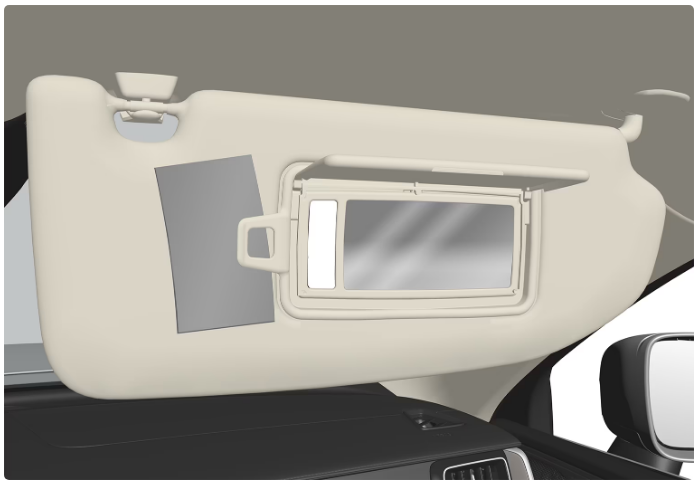 The figure is schematic – the design may vary.
- The mirror lighting is switched on automatically when the guard is lifted up.
- The mirror frame incorporates a holder for e.g. cards or tickets.
Tunnel console
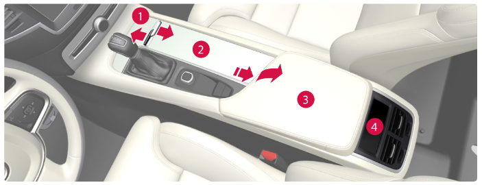 Storage compartment hatch and 12 V socket. The hatch is opened/closed with a push on the handle.
- Storage compartment with cup holder and wireless phone charger.
- Storage compartment and USB ports under the armrest.
- Climate controls for the rear seat climate functions or storage compartment. There are also USB ports underneath.
WarningKeep loose objects such as phones, cameras, remote controls for accessories, etc. in the glove compartment or other compartments. Otherwise, they may injure people in the car in the event of sudden braking or a collision.
ImportantKeep in mind that high gloss surfaces, for example, are easily scratched by metal objects. Do not place keys, phones, and other items on sensitive surfaces.
NoteOne of the detectors for the alarm is located under the tunnel console’s cup holder. Avoid leaving coins, keys, and other metal objects in the cup holder, since this may trigger the alarm.
NoteThe USB ports can be used for charging a phone or tablet, for example. Only the front USB port can be used to play media in the car’s audio system.
Fuses under glovebox
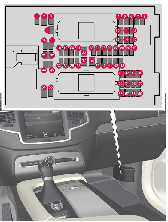 The central electrical unit is located behind the floor mat/side panel.
- The fuse box in the engine compartment provides space for several spare fuses.
Positions
Fuse locations are shown on the inside of the cover. Functions and components in the fuse table cover several models and engine alternatives. A fuse description can therefore apply to fewer than those in the table, or be completely missing, depending on how the car is equipped. If a position has several values in the table, the value depends on variations in equipment level. In which case, follow the value of the fuse being replaced. In the event of doubt – contact a workshop. An authorized Volvo workshop is recommended.
| Function | Ampere | Type | |
|---|---|---|---|
| Control module, 48 V battery | 10 | Micro | |
| – | – | Messe | |
| – | – | Micro | |
| Movement detector | 5 | Micro | |
| – | – | Micro | |
| Driver display | 5 | Micro | |
| Keypad, centre console | 5 | Micro | |
| Sun sensor | 5 | Micro | |
| – | – | Micro | |
| Infotainment module | 15 | Micro | |
| Steering wheel module | 5 | Micro | |
| Control module, start knob, and parking brake | 5 | Micro | |
| Heated steering wheel | 15 | Micro | |
| – | – | Micro | |
| – | – | Micro | |
| – | – | Micro | |
| – | – | Micro | |
| Control module, climate control | 10 | Micro | |
| Steering lock | 7.5 | Micro | |
| Diagnostic port OBD-II | 10 | Micro | |
| Centre display | 5 | Micro | |
| Fan module, climate control, front | 40 | MCase | |
| USB hub | 5 | Micro | |
| Controls lighting
Passenger compartment lighting Dimming, interior rearview mirror Rain and light sensors Power front seats Control panels, rear doors Fan module, climate control |
7.5 | Micro | |
| Control module, driver support functions | 5 | Micro | |
| Overhead console | 20 | Micro | |
| Head-up display | 5 | Micro | |
| Passenger compartment lighting | 5 | Micro | |
| Wireless charging plate | 5 | Micro | |
| Display roof console | 5 | Micro | |
| – | – | Micro | |
| – | – | Micro | |
| – | – | Micro | |
| Fuse box, cargo area | 10 | Micro | |
| Control module, online car
Control module, Volvo On Call |
5 | Micro | |
| – | – | Micro | |
| Audio control device (amplifier) | 40 | MCase | |
| Fan module, climate control, rear | 40 | MCase | |
| Multi-band antenna | 5 | Micro | |
| Control module, seat comfort, front | 5 | Micro | |
| Alcohol lock | 5 | Micro | |
| Rear window wiper | 15 | Micro | |
| Control module, fuel pump | 15 | Micro | |
| Converter 48 V
Engine start module |
5 | Micro | |
| Control module, Intellisafe | 5 | Micro | |
| Seat heating, driver’s side front | 15 | Micro | |
| Seat heating, passenger side front | 15 | Micro | |
| Coolant pump | 7.5 | Micro | |
| – | – | Micro | |
| Power driver’s seat | 20 | Micro | |
| Module, active damping | 20 | Micro | |
| Opening the boot lid/tailgate with foot motion | 5 | Micro | |
| Infotainment module | 10 | Micro | |
| – | – | MCase | |
| – | – | Micro | |
| Electrically operated front passenger seat | 20 | Micro | |
| – | – | Micro | |
| TV (certain markets) | 5 | Micro | |
| Primary fuse for fuses 52, 53, 57 and 58 (Infotainment group) | 15 | Micro |
