
![]()
2022 Land Rover Discovery Wheel Changing

WHEEL CHANGING SAFETY
Make sure to read and fully understand the following warnings. Failure to comply with the safety instructions could result in an accident, leading to serious injury or death.
If in any doubt regarding the ability to carry out the instructions, or comply with warnings, seek assistance.
Always find a safe place to stop, off the highway and away from traffic. Switch on the hazard warning lights to alert all traffic of the obstruction. Apply the Electric Parking Brake (EPB) and engage Park (P). Switch the engine off and remove the smart key from the vehicle.
If available, place a warning triangle at a suitable distance behind the vehicle, facing toward oncoming traffic.
Different countries have different traffic laws. Carrying and/or using warning triangles may be required by law when stopping at the side of a highway. The driver is responsible for staying informed about road regulations, and for complying with local traffic laws.
In an emergency or a breakdown situation, wear a reflective jacket if stopped at the side of the road and working around the vehicle.
Different countries have different traffic laws. Carrying and/or wearing reflective jackets may be required by law. The driver is responsible for staying informed about road regulations, and for complying with local traffic laws.
Make sure that all passengers, and animals, are out of the vehicle and in a safe place, away from the highway.
Make sure that the vehicle and jack are both on firm, level ground. Do not jack the vehicle if it is over a metal grating or manhole cover.
Make sure that the front wheels are in the straight-ahead position and engage the steering lock.
Always use the complete jacking lever assembly throughout the wheel-changing process, to minimize any chance of accidental injury. Position the jack from the side of the vehicle, in line with the appropriate jacking point. Never place anything between the jack and the ground, or between the jack and the vehicle. Do not attempt to raise the vehicle, unless the jack head is fully engaged in the jacking point. Only jack the vehicle using the approved jacking points.
WARNING – THAT NO PERSON SHOULD PLACE ANY PORTION OF THEIR BODY UNDER A VEHICLE THAT IS SUPPORTED BY A JACK.
The jack is designed for wheel changing only. Never work beneath the vehicle with the jack as the only means of support. Always use correctly-rated vehicle support stands, before putting any part of the body beneath the vehicle.
Do not make any alterations or modifications to the jack.
When jacking the vehicle, make sure that all precautions are taken to prevent vehicle movement. As an additional precaution, it is recommended that the wheels of the vehicle are chocked.
When one rear wheel is lifted off the ground, the transmission Park (P) position does not prevent the vehicle from moving. The vehicle can potentially slip off the jack, as the Electric Parking Brake (EPB) operates only on the rear wheels. Use a wheel chock when jacking the vehicle.
Always check the wheel diagonally opposite the wheel to be changed. Check the front of a front wheel or the rear of a rear wheel.
If jacking the vehicle on a slight slope is unavoidable, place the chocks on the downhill side of the two opposite wheels. Two chocks must be used if this is the case.
Take care when loosening the lug nuts. The lug wrench may slip off if not properly attached, and the lug nuts may give way suddenly. Either unexpected movement may cause an injury.
Do not start or run the engine while the vehicle is supported only by a jack.
Remove the spare wheel before jacking the vehicle, to avoid destabilizing the vehicle when raised. Take care when lifting the spare wheel and removing the punctured wheel. The wheels are heavy and can cause injuries if not handled correctly.
After wheel changing, always secure the tools, jack, and the replaced wheel in the correct storage positions. Such objects, if not properly stored, can become propelled objects in a crash or rollover.
TOOL KIT
Make sure the relevant safety warnings have been read and understood before using the tool kit. See WHEEL CHANGING SAFETY.
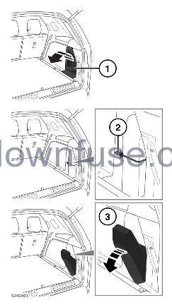
The tool kit is stored behind an access cover on the right side of the loadspace.
To remove the tool kit:
- Rotate the locking tab 90 degrees counter-clockwise. Pull the panel forward and lift it up.
- Release the tool kit’s securing strap.
- Carefully release the top of the tool kit from the aperture and remove the tool kit.
CAUTION
Do not use excessive force when removing the tool kit. The use of excessive force may cause damage to the vehicle.
To fit the tool kit, reverse the removal procedure.
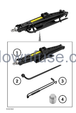
The tool kit consists of:
- Jack.
- Lug wrench.
- Winch tool.
- Locking lug nut adapter.
The winch tool (3) is also used to raise and lower the jack.
Tool types and positions may vary from the illustration.
Examine the jack occasionally. Clean and grease the moving parts, particularly the screw thread, to prevent corrosion.
Take careful note of the storage position for each tool, as it is important to return the tools to their correct positions after use.
REMOVING THE SPARE WHEEL
Make sure to read and fully understand the following warnings. Failure to comply with the safety instructions may result in an accident, leading to serious injury or death.
Make sure the relevant safety warnings have been read and understood before removing the spare wheel. See WHEEL CHANGING SAFETY.
Do not store the wheel while the vehicle is raised on the jack.
When tensioning the winch cable by hand, take care not to trap any fingers.
The spare wheel is located underneath the rear of the vehicle and is released by operating the spare wheel winch.
To access the spare wheel winch:
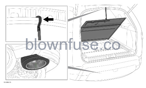
- On 7-seat vehicles: Fold the loadspace floor panel forward.
- On 5-seat vehicles: Lift the loadspace floor panel. Secure the loadspace floor panel in the upright position using the strap, as illustrated.
Do not use power tools to lower the spare wheel. Doing so may damage the mechanism.
Do not operate the winch, retracting or extracting the cable, without pre-tensioning the cable. Doing so may cause damage to the winch. Pre-tensioning can be achieved, either with the weight of a spare wheel or a road wheel or by maintaining tension using a hand.
Remove any tools stored above the winch to allow access.
Before removing the spare wheel, take note of its storage position. The wheel to be changed must be correctly stored and secured in its place.
It is recommended that the road wheel is always stored underneath the vehicle following a puncture.
Always store a road wheel and the spare wheel with the outer face of the wheel facing upward.
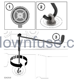
- Remove the grommet for access to the spare wheel winch.
NOTES
Make sure to refit the grommet after the wheel change is complete.
- Fit the winch tool to the spare wheel winch and rotate counter-clockwise to lower the spare wheel.
- Rotate the winch tool until the spare wheel is on the ground and the winch cable is slack.
CAUTION
Do not attempt to turn the winch beyond the physical stop.
To release the wheel from the winch:
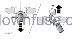
Lift the spare wheel, and pass the winch cable through the center of the wheel to release it, as shown in the above graphic.
To store the removed road wheel:
- Remove the center cap from the road wheel and store it in a safe place.
- Position the road wheel underneath the rear of the vehicle, with the outer face of the road wheel facing upward.
- Pass the winch cable through the center of the wheel.
- Start to turn the winch handle clockwise to take the slack out of the cable. Make sure the cable end is seated correctly before continuing to raise the wheel.
- Continue to rotate the winch handle until the road wheel is in the stored position.
- Remove the winch handle and store all of the tools and the jack in their original positions.
When extracting the winch cable after the winch cable has been retracted without a road wheel attached, operate the winch as follows:
Fit the winch handle to the spare wheel winch and rotate counter-clockwise to extract the cable. While rotating the winch, apply tension by pulling on the end of the winch cable.
If, while the cable is being extracted, the winch feels tight or locks up, stop winding and wind back, at least one full turn. Apply tension on the cable to release any cable slack, if necessary, giving it a sharp tug. Try the winch again and continue if the mechanism is free to operate. Repeat, if the winch feels tight or locks up again.
If the winch feels tight or locks up, stop winding and wind back, at least one full turn. If this fails to free the winch mechanism, do not continue, as damage may be caused to the winch.
IMPORTANT – USE OF SPARE TIRE
Make sure to read and fully understand the following warnings. Failure to comply with the safety instructions could result in an accident, leading to serious injury or death.
Adhere to the instructions on the temporary-use spare wheel’s warning label, affixed to the wheel. Failure to do so may cause vehicle instability and/or tire failure.
Where fitted, the temporary-use spare wheel is for temporary use only.
Drive with caution while the temporary-use spare wheel is fitted.
Make sure that an original size wheel and tire are fitted as soon as possible.
Do not fit more than one temporary-use spare wheel at any one time.
Do not exceed 50 mph (80 km/h) while the temporary-use spare wheel is fitted.
The temporary-use spare wheel must be inflated to 60 psi (4.2 bar, 420 kPa) and cannot be repaired.
Dynamic Stability Control (DSC) must be switched on while the temporary-use spare wheel is in use.
Traction devices, such as snow chains, cannot be used with a temporary-use spare wheel.
Before removing the spare wheel, take note of its storage position. The wheel to be changed must be correctly stored and secured in its place.
USING WHEEL CHOCKS
Make sure the relevant safety warnings have been read and understood before using wheel chocks. Failure to comply with the safety instructions could result in an accident, leading to serious injury or death. See WHEEL CHANGING SAFETY.
Wheel chocks are a useful addition to a vehicle’s tool kit. If required, a wheel chock can be stored with the vehicle’s tool kit. See TOOL KIT.
LOCKING LUG NUTS
When the vehicle is first supplied, the locking lug nut adapter may be stored in the glove box. If this is the case, the locking lug nut adapter must be moved to its correct storage position in the loadspace, as soon as possible. See TOOL KIT.
Not all vehicles have locking lug nuts as standard parts.
The locking lug nut adapter must be correctly aligned and fully fitted to the locking lug nut before usage. Incorrect fitment can result in permanent damage to the locking lug nut adapter. Incorrect fitment can cause the locking lug nut’s anti-tamper device to rotate, preventing the removal of the locking lug nut. If in doubt, contact a retailer/authorized repairer.
Do not use air tools or power tools to remove or refit the locking lug nut. Doing so may damage the locking lug nut or the locking lug nut adapter.
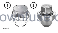
Depending on the vehicle specification, two different locking lug nuts, (1) and (2), are fitted to the vehicle.
Locking lug nuts can be removed and fitted using only the special locking lug nut adapter provided. See TOOL KIT.
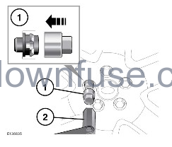
To release the locking lug nut:
- Insert the adapter into the locking lug nut, making sure that it is fully engaged.
- Using the lug wrench, unscrew the lug nut and adapter.
- After raising the vehicle on the jack, remove the locking lug nut.
The locking lug nut, shown below, and locking lug nut adapter contain two anti-tamper features.
If the locking lug nut adapter is forced onto the locking lug nut, the adapter may be damaged beyond repair.
If the locking lug nut adapter is not fully engaged, the cap on the locking lug nut rotates. To allow the locking lug nut to be fully tightened or removed, the locking lug nut cap must be reset.
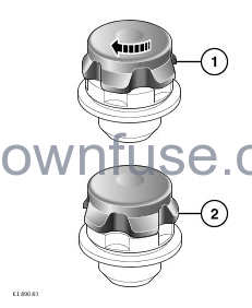
The locking lug nut cap can be reset as follows:
- Carefully fit the locking lug nut adapter onto the locking lug nut cap and rotate the cap counterclockwise.
- Rotate the locking lug nut cap counter-clockwise until all of the grooves on the cap align exactly with the locking lug nut grooves.
Should a replacement locking lug nut adapter be required, consult an authorized retailer. It is advised to make a note of the locking lug nut adapter code number to allow a replacement to be sourced if ever required. Depending upon the specification of the locking lug nut adapter, the code may be stamped on the locking lug nut adapter or supplied on a separate card.
| Locking lug nut adapter code number |
WHEEL CHANGING
Make sure to read and fully understand the following warnings. Failure to comply with the safety instructions could result in an accident, leading to serious injury or death.
Make sure the relevant safety warnings have been read and understood before changing a wheel. See WHEEL CHANGING SAFETY.
Disconnect any trailer or caravan from the vehicle.
The standard vehicle jacking points should be used to raise the vehicle. Do not raise the vehicle by jacking under the side steps, or side tubes.
Only jack the vehicle using the jacking points described, or damage to the vehicle could occur.
Before raising the vehicle:
- Remove the required tools from the vehicle. See TOOL KIT.
- Remove the spare wheel. See REMOVING THE SPARE WHEEL.
- Correctly position the wheel chocks. See WHEEL CHANGING SAFETY.
To change a wheel:
- Use the lug wrench to loosen the lug nuts of the wheel to be replaced. Turn half a turn counter-clockwise.
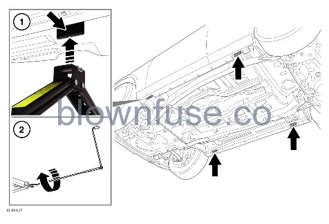
- Locate the jack under the relevant jacking point (1).
CAUTION
Do not allow the jack to contact the sill at any other point, as damage may result.
- Rotate the jack handle (2) clockwise until the jack locates at the jacking point.
- Raise the vehicle until the wheel is clear of the ground.
WARNING
Avoid rapid, jerky actions. Rapid, jerky actions may cause the vehicle and jack to become unstable, which may result in an accident, leading to serious injury or death.
- Remove the lug nuts and place them together where they cannot roll away.
- Remove the wheel and place on one side.
CAUTION
Do not lay the wheel on its face, as this may damage the finish.
- Fit the spare wheel to the hub.
- Refit the lug nuts and lightly tighten them. Make sure that the wheel is making contact with the hub evenly.
- Make sure that the space under the vehicle is clear of obstructions. Lower the vehicle slowly and smoothly.
- With all of the wheels on the ground and the jack removed, fully tighten the lug nuts. The lug nuts must be tightened in sequence, as illustrated, to the correct torque of 103 lb.ft (140 Nm).

If it is not possible to torque the lug nuts when a wheel is replaced, they should be set to the correct torque as soon as possible.
If an alloy spare wheel is to be fitted, using a suitable blunt tool, knock the center cap out of the removed wheel. Using hand pressure only, press the center cap into the newly fitted spare.
Check and adjust the tire pressure as soon as possible.
VEHICLES WITH FIXED SIDE STEPS, DEPLOYABLE SIDE STEPS, OR SIDE TUBES:
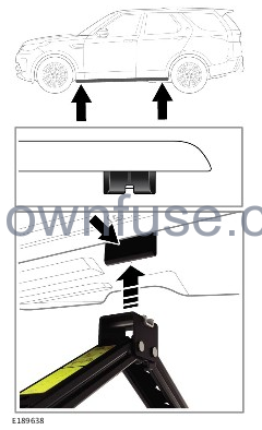
The deployable side steps must be in the stored position and the system switched off when raising the vehicle. Failure to do so may result in an accident, leading to serious injury or death.
- Do not raise the vehicle with the deployable side steps in the deployed position. Doing so may result in an accident, leading to serious injury or death.
- If the vehicle is fitted with deployable side steps, fixed side steps, or side tubes, the standard vehicle jacking points are obscured.
- To raise the vehicle, use the jacking points located at the front and rear of the side tubes, fixed side steps, or deployable side steps to raise the vehicle.