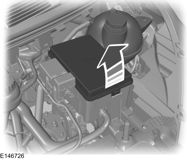
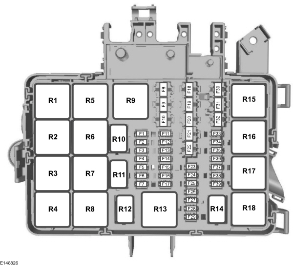
FUSE BOX LOCATIONS Engine Compartment Fuse Box
FUSE SPECIFICATION CHART Engine Compartment Fuse Box
Fuse Fuse rating Circuits protected F1 10A Selective Catalytic Reduction – Diesel. F2 15A Selective Catalytic Reduction – Diesel. F3 15A Selective Catalytic Reduction – Diesel. F4 10A Selective Catalytic Reduction – Diesel. F5 3A Diesel particulate filter vaporizer. Glow plug monitor. F6 3A Anti-lock brake system. Stability assist. Ignition. F7 7.5A Powertrain control module. F8 20A Cooling fan – Gasoline. F9 30A Left-hand windshield wiper. F10 30A Right-hand windshield wiper. F11 10A Air conditioning clutch. F12 20A Diesel particulate filter vaporizer glow plug. F13 – Not used. F14 3A Selective Catalytic Reduction – ignition – Diesel. F15 – Not used. F16 – Not used. F17 – Not used. F18 40A Anti-lock brake system. Stability assist pump. F19 30A Starter solenoid. F20 60A Glow plugs. F21 60A Ignition relay 3. F22 40A Selective Catalytic Reduction relay feed. F22 40A Electric vacuum pump relay feed. F23 10A PROTECTED CIRCUIT FUSE. F24 10A Fuel injection pump – Diesel. F24 20A Fuel injection pump – Gasoline. F25 15A Throttle control unit – Diesel. F25 10A PROTECTED CIRCUIT FUSE – Gasoline. F26 20A PROTECTED CIRCUIT FUSE. F27 – Not used. F28 7.5A Crankcase sensor – Diesel. F28 10A Injection power – Gasoline 3.7L. F29 3A Ignition feed – Audio – Gasoline. F29 7.5A Crank case ventilation heater – Diesel. F30 60A Single cooling fan. F30 40A Twin cooling fan. F31 40A Twin cooling fan 2 – Gasoline. F32 30A Windshield wiper motor. F32 60A Windshield dual wiper motors. F33 20A Start-Stop auxiliary water pump. F34 – Not used. F35 20A Powertrain control system supply – Gasoline. F35 15A Powertrain control system supply – Diesel. F36 20A Mass air flow sensor – Gasoline. F36 15A Mass air flow sensor . NOX sensor 1, 2 – Diesel. F37 7.5A Volume Control Valve. F38 20A Air conditioning clutch – Gasoline. F38 7.5A Air conditioning clutch – Diesel. F39 10A UEGO, VAP PUMP, EBYPASS, EDF, HEDF – Gasoline. F39 15A UEGO, VAP PUMP, EBYPASS, EDF, HEDF – Diesel.
Relay Circuits switched R1 Ignition 3. R2 Not used. R3 Not used. R4 Not used. R5 Cooling fan – Gasoline. R6 Windshield wiper – on and off. R7 Windshield wiper – low and high speed. R8 Electrical Vacuum Pump – Gasoline. R9 Starter motor. R10 Air conditioning clutch. R11 Fuel vaporizer system glow plug. R12 Fuel injection pump. R13 Not used. R14 Not used. R15 Low-speed and high-speed cooling fan. R16 Selective Catalytic Reduction – Diesel. R17 Powertrain control module. R18 High speed cooling fan.
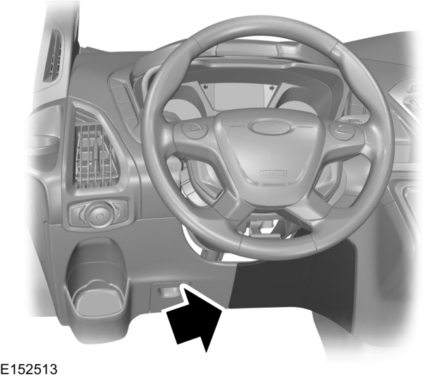
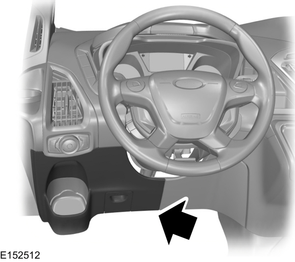
Passenger Compartment Fuse Panel
Fuse Fuse rating Circuits protected F1 10A Airbag module. F2 4A Anti-lock brake system with electronic stability control. Parking brake. F3 – Not used. F4 10A Trailer tow back-up lamp relay. F5 20A Cutaway body connectors. F6 – Not used. F7 – Not used. F8 40A AC power outlet socket. F9 30A Trailer brake module. F10 30A Driver power seat. F11 30A Passenger power seat. F12 30A Trailer tow park lamp relay. F13 25A Anti-lock brake system with electronic stability control valves. F14 5A Powertrain control module B+ relay. F15 40A Powertrain control module power relay. F16 40A Body control module power feed. F17 40A Ignition relay 3. F18 40A Modified vehicle connections. F19 – Not used. F20 5A Heated exterior mirror relay. F21 10A Modified vehicle ignition connections. F22 15A Passenger compartment fuse panel. F23 7.5A Air conditioning control module. F24 10A Cutaway body connectors. F25 7.5A Interior lighting. F26 10A Heated exterior mirrors. F27 20A Heated rear window. F28 20A Heated rear window. F29 10A Rear parking aid camera. Lane keeping system. Electro mirror. F30 – Not used. F31 10A Trailer brake ignition feed. F32 10A Interior lighting. F33 – Not used. F34 – Not used. F35 5A Power folding mirrors. F36 20A Horn. F37 7.5A SYNC module. F38 5A Blower motor. Horn relay. Windshield wiper relay. F39 7.5A Remote keyless entry. Battery. Power windows. Rear heating, ventilation and air conditioning. F40 40A Front blower motor. F41 40A Rear blower motor. F42 40A Heated rear window. F43 30A Trailer socket. F44 60A Auxiliary power points. F45 40A Trailer connectors B+ supply. F46 30A Power windows. F47 20A Cigar lighter socket. F48 20A Rear auxiliary power points. F49 20A Front auxiliary power points. F50 60A Ignition relay 1. F51 60A Ignition relay 2. F52 40A Modified vehicle connections. F53 40A Modified vehicle connections.
Relay Circuits switched R1 Not used (spare). R2 Auxiliary power points. R3 Trailer tow parking lamp. R4 Ignition 2. R5 Power windows. R6 Ignition 1. R7 Horn. R8 Trailer tow back-up lamp. R9 Front blower motor. R10 Rear blower motor. R11 Heated rear window. Heated exterior mirrors. R12 Not used. R13 Modified vehicle connections.
Pre-fuse Box
Fusible link Fusible link rating Circuits protected C 470A Engine compartment fuse box. Starter motor. Alternator. D 100A Passenger compartment fuse panel. Body control module fuse box. E 40A Powertrain control module. Anti-lock brake system. F 200A Passenger compartment fuse panel. G 100A Passenger compartment fuse panel. H 80A Positive temperature coefficient heater. J – Not used. K 100A Engine junction box feed. L 100A Passenger compartment fuse panel. M 60A Passenger compartment fuse panel supply. N 60A Passenger compartment fuse panel supply. P 60A Auxiliary power point 1. R 60A Auxiliary power point 2. S 60A Auxiliary power point 3.
Fuse Fuse rating Circuits protected F1 – Not used. F2 – Not used. F3 – Not used. F4 – Not used. F5 20A R4 relay power. F6 20A R3 relay power. F7 20A R2 relay power. F8 20A R1 relay power. F9 – Not used. F10 – Not used. F11 – Not used. F12 3A Switch power.
Relay Circuits switched R1 Upfitter 1. R2 Upfitter 2. R3 Upfitter 3. R4 Upfitter 4. R5 Not used. R6 Not used. R7 Not used.
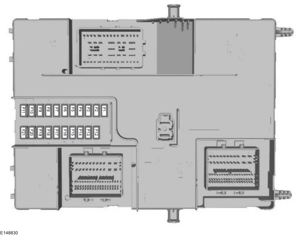
Body Control Module
Fuse Fuse rating Circuits protected F1 15A Central locking system 2. F2 15A Central locking system 1. F3 15A Ignition switch. F4 5A Parking assist control module. Brake transmission shift interlock. F5 5A Rain sensor module. F6 15A Windshield washer pump. F7 – Not used. F8 – Not used. F9 10A Right-hand high beam. F10 10A Left-hand high beam. F11 25A Right-hand exterior lamps. Left-hand position lamps. F12 – Not used. F13 15A On-board diagnostic. Battery saver. F14 25A Turn signal indicator. Power windows delayed accessory. Lane departure sensor heated windshield pad. F15 25A Left-hand exterior lamps. Right-hand position lamps. High mounted stoplamp. F16 20A Audio unit. Navigation unit. F17 7.5A Instrument panel cluster. Heater control. F18 10A Headlamp switch module. Steering wheel module. Stoplamp switch supply. F19 5A Front control/display interface module. F20 5A Ignition passive anti-theft system. F21 3A Accessory relay, customer access feed.
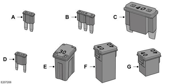
CHANGING A FUSE Fuses
WARNING : Always replace a fuse with one that has the specified amperage rating. Using a fuse with a higher amperage rating can cause severe wire damage and could start a fire.
Callout Fuse Type A Micro 2 B Micro 3 C Maxi D Mini E M Case F J Case G J Case Low Profile
To download the complete user manual, please download the following file:
https://www.fordservicecontent.com/Ford_Content/vdirsnet/OwnerManual/Home/Index?Variantid=3230&languageCode=EN&countryCode=USA&marketCode=US&bookcode=O25365&VIN=&userMarket=usa&div=f


 WARNING: Always replace a fuse with one that has the specified amperage rating. Using a fuse with a higher amperage rating can cause severe wire damage and could start a fire.