
Below are the locations and diagrams for all fuse boxes on a 2021 Ford Ranger.
2021 Ford Ranger Owners Manual
Fuse Box Locations
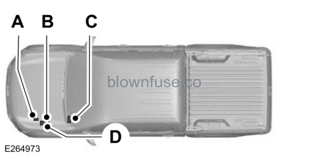
| A B C D Note: The passenger compartment fuse box is on the right-hand side for right-hand drive vehicles. |
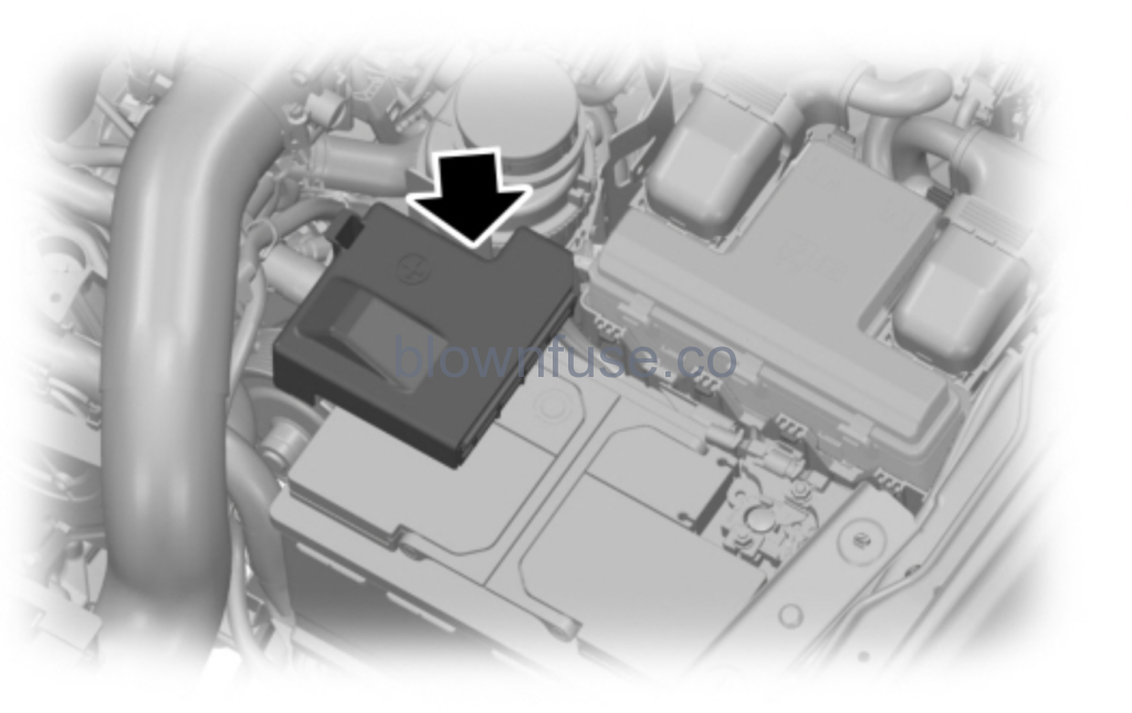
Pre-fuse Box Location
Your vehicle has a pre-fuse box in the engine compartment attached to the positive battery post. This box contains several high current fuses. If replacement of these high current fuses is required, see an authorized dealer.
Pre-fuse Box Diagram
| Fuse Number | Fuse Rating | Protected Component |
|---|---|---|
| 1 | 300A | Alternator (with auxiliary fuse and relay box). |
| 225A | Alternator (without auxiliary fuse and relay box). | |
| 2 | 125A | Electronic power assist steering. |
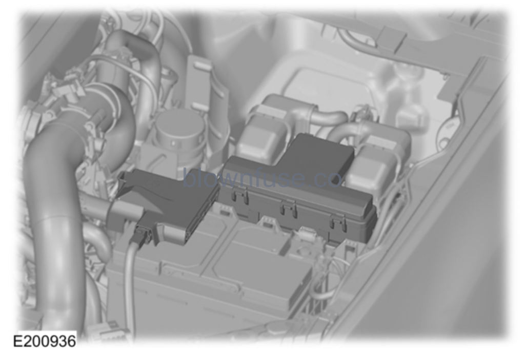
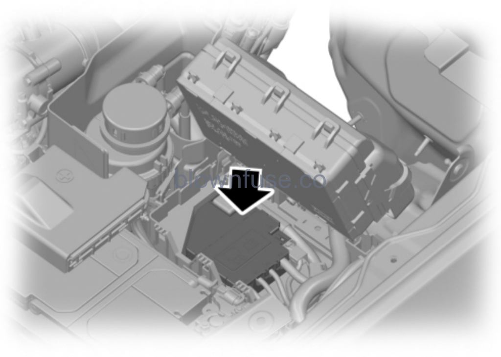
Engine Compartment Fuse Box Location
WARNING: Always disconnect the battery before servicing high current fuses. WARNING: To reduce risk of electrical shock, always replace the cover to the power distribution box before reconnecting the battery or refilling fluid reservoirs. WARNING: To reduce risk of electrical shock, always replace the cover to the power distribution box before reconnecting the battery or refilling fluid reservoirs. |
The engine compartment fuse box has high-current fuses that protect your vehicle’s main electrical systems from overloads.When you disconnect and reconnect the battery, you need to reset some features. Lift the release lever at the rear of the cover to remove it.
Engine Compartment Fuse Box Diagram
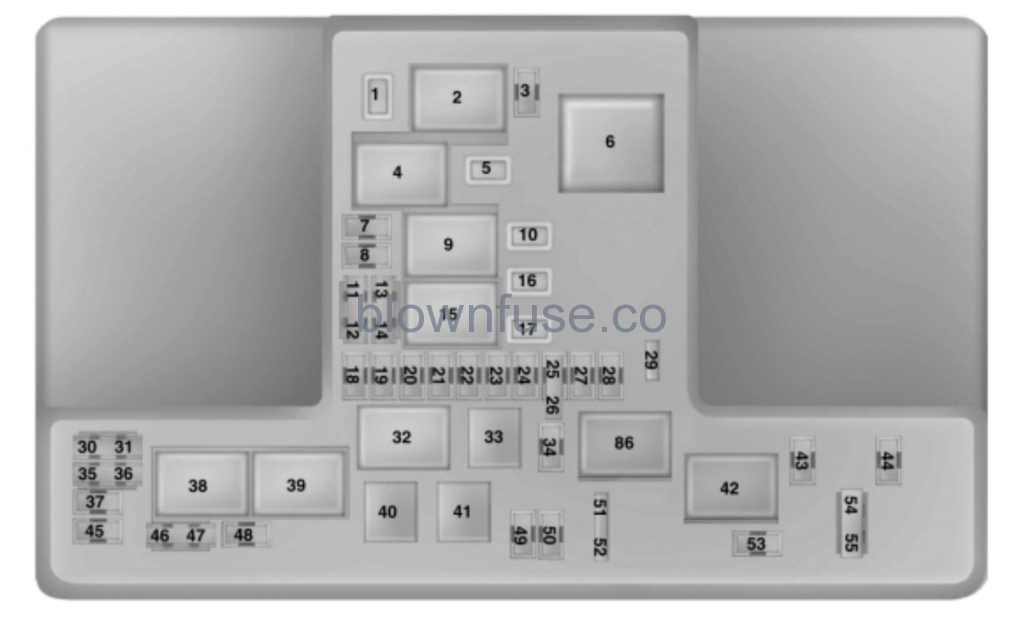
| Fuse or Relay Number | Fuse Rating | Protected Component |
|---|---|---|
| 1 | 15A1 | Not used (spare). |
| 2 | – | Starter motor solenoid relay. |
| 3 | 5A2 | Rain sensor. |
| 4 | – | Blower motor relay. |
| 5 | 20A1 | Auxiliary power point 3 – console rear. |
| 6 | – | Trailer park lamp relay. |
| 7 | 20A2 | Powertrain control module. |
| 8 | 20A2 | Canister vent solenoid. Fuel vapor shutoff valve. Canister purge valve. Variable cam timing valve 1 and 2. Heated oxygen sensors. |
| 9 | – | Powertrain control module relay. |
| 10 | 20A1 | Auxiliary power point 1 – instrument panel. |
| 11 | 15A3 | Ignition coils. |
| 12 | 15A3 | A/C control drive. Transaxle warmer. Auxiliary water pump. Aspirator valve control. Fan clutch. Oil pump. Turbo bypass. |
| 13 | 15A3 | Not used (spare). |
| 14 | 15A3 | Not used (spare). |
| 15 | – | Run/start relay. |
| 16 | 20A1 | Auxiliary power point 2 – instrument panel. |
| 17 | 20A1 | Auxiliary power point – rear cargo area. |
| 18 | 10A2 | Not used (spare). |
| 19 | 10A2 | Electric power assist steering. |
| 20 | 10A2 | Lighting control switch. |
| 21 | 5A2 | Transmission Run/Start relay. |
| 22 | 10A2 | Air conditioning compressor. |
| 23 | 7.5A2 | Voltage quality module. |
| 24 | 10A2 | Not used (spare). |
| 25 | 10A3 | Anti-lock brake system. |
| 26 | 10A3 | Not used (spare). |
| 27 | – | Not used. |
| 28 | 10A2 | Powertrain control module. |
| 29 | 7.5A2 | USB charge port. |
| 30 | – | Not used. |
| 31 | – | Not used. |
| 32 | – | Fuel pump relay. |
| 33 | – | A/C clutch relay. |
| 34 | 10A2 | Trailer reverse lamp. |
| 35 | 15A2 | Not used (spare). |
| 36 | – | Not used. |
| 37 | 10A2 | Heated exterior mirror. |
| 38 | – | Trailer right-hand turn and stop lamp relay. |
| 39 | – | Trailer left-hand turn and stop lamp relay. |
| 40 | – | Trailer reverse lamp relay. |
| 41 | – | Horn relay. |
| 42 | – | motor no. 2 relay. |
| 43 | – | Not used. |
| 44 | – | Not used. |
| 45 | 5A2 | Not used (spare). |
| 46 | 10A3 | Not used (spare). |
| 47 | 10A3 | Brake pedal switch. |
| 48 | 20A2 | Horn. |
| 49 | 15A2 | Transmission control module. Oil pump. |
| 50 | 10A2 | Wiper park heater. |
| 51 | – | Not used. |
| 52 | – | Not used. |
| 53 | 15A2 | Rear differential lock. |
| 54 | – | Not used. |
| 55 | – | Not used. |
| 86 | – | motor no. 1 relay. |
1M-type fuse.2Micro 2 fuse.3Micro 3 fuse.
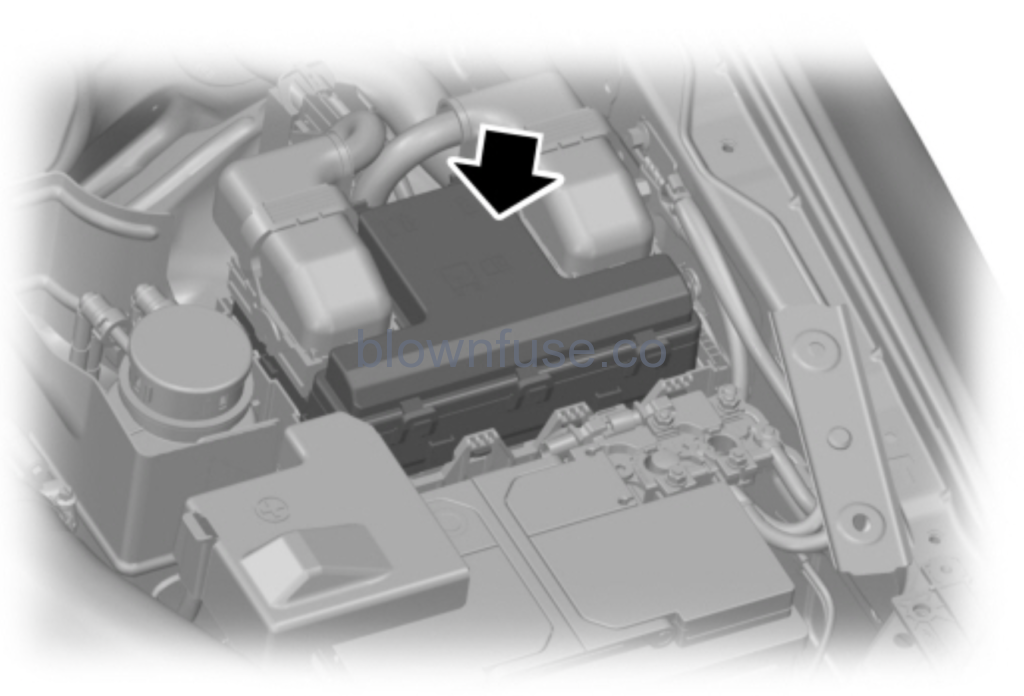
High Current Fuse Box Location (Under Power Distribution Box)
Your vehicle has a pre-fuse box in the engine compartment below the engine compartment fuse box. This box contains several high current fuses. If replacement of these high current fuses is required, see an authorized dealer.
High Current Fuse Box Diagram
| Fuse Number | Fuse Rating | Protected Component |
|---|---|---|
| 1 | – | Not used. |
| 2 | 125A | Body control module. |
| 3 | 50A | Voltage quality module (supplies rear lamp blind spot, rear view camera, head up display, 4×4 switch, image processing module and adaptive cruise control radar). |
| 4 | – | Busbar through to power distribution box. |
| 5 | 100A | Auxiliary fuse and relay box. |
Bottom of Power Distribution Fuse Box Location
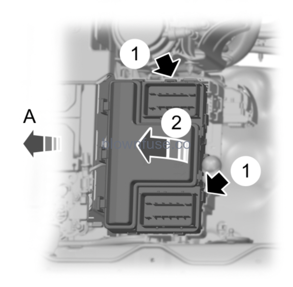
| A |
- Release the two latches on both sides of the fuse box.
- Raise the rear side of the fuse box from the cradle.
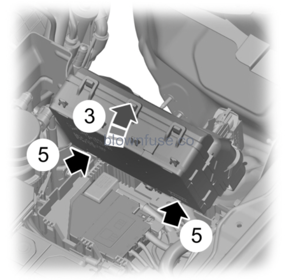
- Move the fuse box toward the rear side of the engine compartment and rotate as shown.
- Pivot the rear side of the fuse box to access the bottom side.
- Release the two latches to open the fuse cover.
Power Distribution Fuse Box Diagram (Bottom of Power Distribution Box)
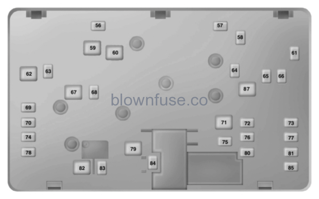
| Fuse or Relay Number | Fuse Rating | Protected Component |
|---|---|---|
| 56 | 15A4 | Trailer left-hand turn and stop. |
| 57 | – | Not used. |
| 58 | – | Not used. |
| 59 | – | Not used. |
| 60 | 30A5 | Fuel pump control module. |
| 61 | – | Not used. |
| 62 | 50A5 | Body control module 1 – lighting. |
| 63 | 15A4 | Trailer right-hand turn and stop. |
| 64 | 30A4 | Trailer brakes. |
| 65 | 20A4 | Heated driver seat. |
| 66 | 25A4 | Four-wheel drive. |
| 67 | 50A5 | Body control module 2 – lighting. |
| 68 | 30A4 | Rear window defroster. |
| 69 | 30A4 | Anti-lock brake system valves. |
| 70 | 30A4 | Passenger power seat. |
| 71 | 25A5 | Trailer park lamps. |
| 72 | – | Not used. |
| 73 | 30A4 | Trailer module. |
| 74 | 30A4 | Driver power seat. |
| 75 | – | Not used. |
| 76 | – | Not used. |
| 77 | – | Not used. |
| 78 | – | Not used. |
| 79 | 40A5 | Blower motor. |
| 80 | 20A4 | Heated passenger seat. |
| 81 | 40A4 | Inverter. |
| 82 | 60A5 | Anti-lock brake system pump. |
| 83 | 30A4 | Windshield wiper motor. |
| 84 | 30A4 | Starter motor solenoid. |
| 85 | – | Not used. |
| 87 | 40A5 | Trailer module. |
4M-type fuse.5LPJ-type fuse.
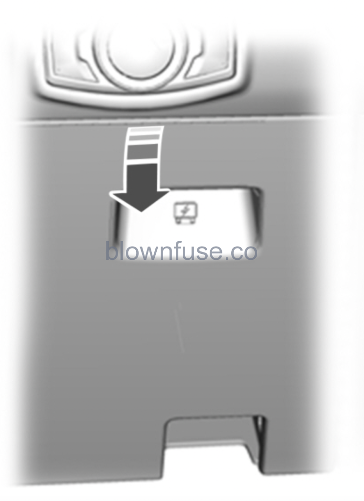
Passenger Compartment Fuse Box Location
The fuse box is behind the access cover on the outermost side of the steering column.
Passenger Compartment Fuse Box Diagram
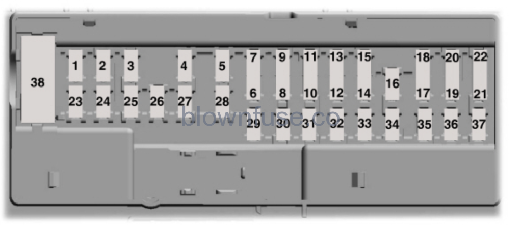
| Fuse or Relay Number | Fuse Rating | Protected Component |
|---|---|---|
| 1 | – | Not used. |
| 2 | 7.5A6 | Not used (spare). |
| 3 | 20A6 | Driver door lock. |
| 4 | 5A6 | Not used (spare). |
| 5 | 20A6 | Branded audio amplifier. |
| 6 | 10A7 | Not used (spare). |
| 7 | 10A7 | Not used (spare). |
| 8 | 10A7 | Anti-theft alarm horn. |
| 9 | 10A7 | Telematics. |
| 10 | 5A7 | Not used (spare). |
| 11 | 5A7 | Not used (spare). |
| 12 | 7.5A7 | Electronic control panel. Climate control. |
| 13 | 7.5A7 | Instrument cluster. Steering column control module. Data link connector. |
| 14 | 10A7 | Extended power module (for restraints module and occupant module). |
| 15 | 10A7 | SYNC Module. Data link connector. |
| 16 | 15A6 | Not used (spare). |
| 17 | 5A7 | Not used (spare). |
| 18 | 5A7 | Ignition switch. Lock solenoid. Push button start. |
| 19 | 7.5A7 | Extended power module (for restraints module and occupant module). |
| 20 | 7.5A7 | Auxiliary switches. |
| 21 | 5A7 | Humidity and in-car temperature sensor. |
| 22 | 5A7 | Not used (spare). |
| 23 | 10A6 | Inverter. Door lock switch. |
| 24 | 20A6 | Central locking system. |
| 25 | 30A6 | Driver door power window. |
| 26 | 30A6 | Not used (spare). |
| 27 | 30A6 | Not used (spare). |
| 28 | 20A6 | Branded audio amplifier. |
| 29 | 30A6 | Not used (spare). |
| 30 | 30A6 | Not used (spare). |
| 31 | 15A6 | SYNC. |
| 32 | 10A6 | Radio transceiver module. Door entry remote. |
| 33 | 20A6 | Audio unit. |
| 34 | 30A6 | Run/start relay. |
| 35 | 5A6 | Not used (spare). |
| 36 | 15A6 | Auto-dimming interior mirror. Mirror adjustment control. |
| 37 | 20A6 | Not used (spare). |
| 38 | 30A8 | Power windows. |
6Micro 2 fuse.7Micro 3 fuse.8PTC fuse.
2021 Ford Ranger Owners Manual