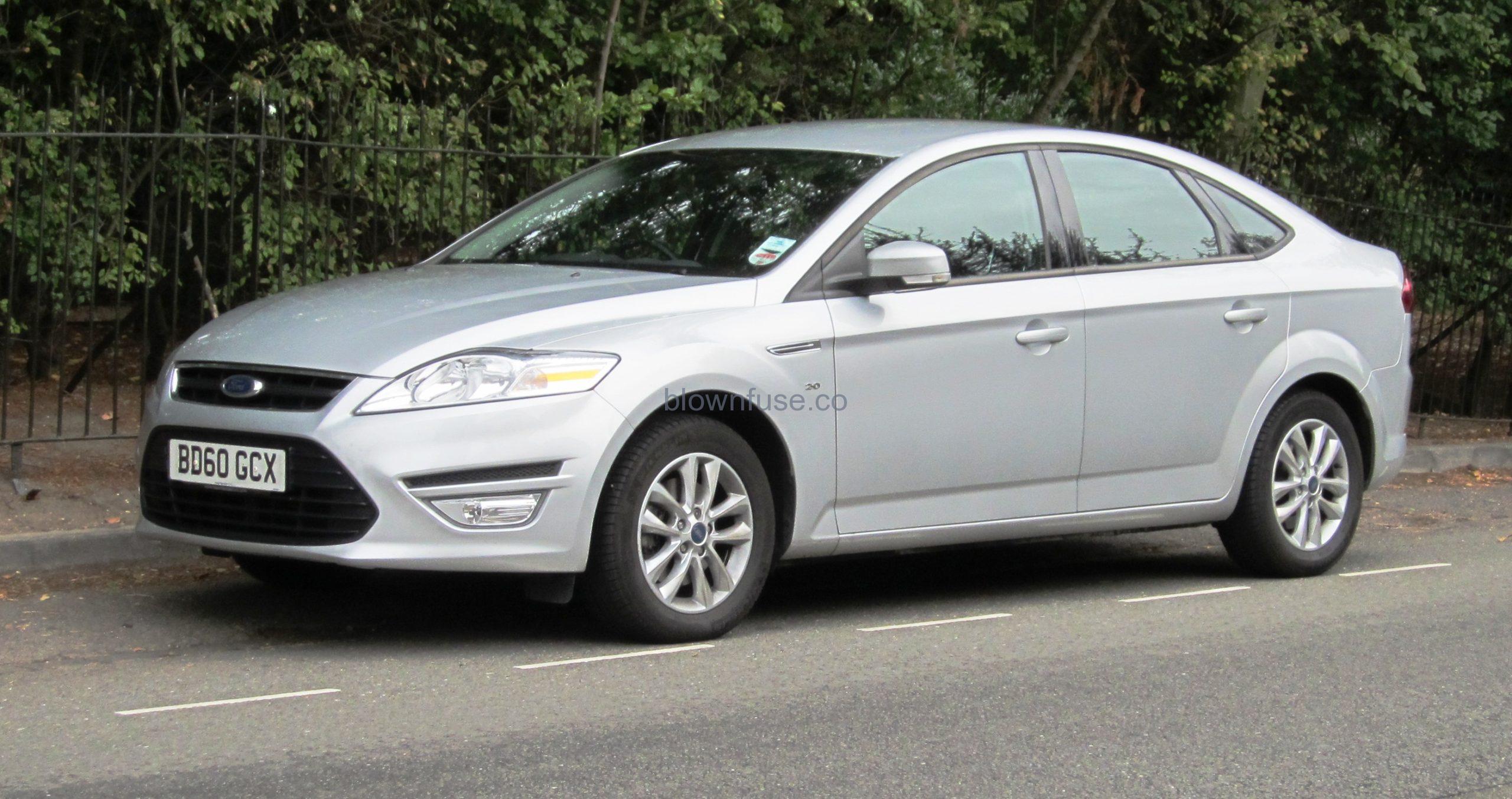
Mondeo Fuse Box Diagram


FUSE SPECIFICATION CHART – EXCLUDING: HYBRID ELECTRIC VEHICLE (HEV)
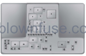
Power Distribution Box


| Fuse Or Relay Number | Fuse Amp Rating | Protected Components |
|---|---|---|
| 1 | 25A 1 | RH front wiper motor. |
| 2 | — | Starter relay. |
| 3 | 15A 2 | Autowipers (rain sensor). Rear wipers. |
| 4 | — | Blower motor relay. |
| 5 | 20A 1 | Back of console auxiliary power point. |
| 6 | — | Auxiliary heater relay. |
| 7 | 20A 2 | Powertrain control module. |
| 8 | 20A 2 | Powertrain control module. |
| 9 | — | Powertrain control module relay. |
| 10 | 20A 1 | Driver front auxiliary power point. |
| 11 | 15A 3 | Powertrain control module. |
| 12 | 15A 3 | Powertrain control module. |
| 13 | 10A 3 | Powertrain control module. |
| 14 | 10A 3 | Powertrain control module. |
| 15 | — | Run-start relay. |
| 16 | 20A 1 | Console auxiliary power point. |
| 17 | 20A 1 | Trunk auxiliary power point (wagon only). |
| 18 | 10A 2 | Powertrain control module. |
| 19 | 10A 2 | Power steering. |
| 20 | 10A 2 | Headlamps. Headlamp switch. |
| 21 | 15A 2 | Transmission control module. Transmission oil pump. |
| 22 | 10A 2 | Air conditioning. |
| 23 | 15A 2 | Blind spot monitor. Rear view camera. Adaptive Cruise Control. Pre-collision warning indicator. Voltage quality module. Air quality sensor. |
| 24 | 10A 2 | Not used (spare). |
| 25 | 10A 3 | Anti-lock brake system. |
| 26 | 10A 3 | Powertrain control module. |
| 27 | — | Not used. |
| 28 | 10A 2 | Rear washer pump. |
| 29 | — | Not used. |
| 30 | — | Not used. |
| 31 | — | Not used. |
| 32 | — | Cooling fan relay. |
| 33 | — | Air conditioning relay. |
| 34 | 15A 2 | Electric steering column lock. |
| 35 | — | Not used. |
| 36 | — | Not used. |
| 37 | — | Not used. |
| 38 | — | Cooling fan relay. |
| 39 | — | Cooling fan relay. |
| 40 | — | Not used. |
| 41 | — | Horn relay. |
| 42 | — | Fuel pump relay. |
| 43 | — | Not used. |
| 44 | 5A 2 | Heated washer nozzle. |
| 45 | — | Not used. |
| 46 | 10A 3 | Alternator. |
| 47 | 10A 3 | Brake on-off switch. |
| 48 | 20A 2 | Horn. |
| 49 | 5A 2 | Mass air flow monitor. |
| 20A 2 | Fuel heater element-Diesel. | |
| 50 | 10A 2 | Power transfer unit cooling fan. |
| 51 | — | Not used. |
| 52 | — | Not used. |
| 53 | 10A 2 | Power seats. |
| 54 | 5A 3 | Fuel operated heater remote control. |
| 55 | 5A 3 | Not used (spare). |
1M-type fuse.2Micro fuse.3Dual micro fuse.Power Distribution Box – BottomThere are fuses located on the bottom of the fuse box. To reach the bottom of the fuse box:
Power Distribution Box – Bottom
There are fuses located on the bottom of the fuse box. To reach the bottom of the fuse box:
- Release the two latches, located on both sides of the fuse box.
- Raise the inboard side of the fuse box from the cradle.
- Move the fuse box toward the center of the engine compartment.
- Pivot the outboard side of the fuse box to reach the bottom side.
| Fuse Or Relay Number | Fuse Amp Rating | Protected Component |
|---|---|---|
| 56 | — | Not used. |
| 57 | 20A 4 | Diesel vaporizer. |
| 58 | 30A 4 | Fuel pump. |
| 59 | 30A 5 | Cooling fan. |
| 40A 5 | Cooling fan (DW10F and 2.0L GTDI AU). | |
| 60 | 30A 5 | Cooling fan. |
| 40A 5 | Cooling fan (DW10F and 2.0L GTDI AU). | |
| 61 | 40A 4 | Left-hand heated windshield element. |
| 62 | 50A 5 | Body control module. |
| 63 | 25A 4 | Cooling fan. |
| 30A 4 | Cooling fan (DW10F and 2.0L GTDI AU). | |
| 64 | 30A 4 | Auxiliary heater. |
| 65 | 20A 4 | Front heated seat. |
| 66 | 40A 4 | Right-hand heated windshield element. |
| 67 | 50A 5 | Body control module. |
| 68 | 40A 4 | Heated rear window. |
| 69 | 30A 4 | Anti-lock brake system. |
| 70 | 30A 4 | Passenger seat. |
| 71 | 60A 5 | Auxiliary heater. |
| 72 | 30A 4 | Moonroof. |
| 73 | 20A 4 | Rear heated seat. |
| 74 | 30A 4 | Driver seat module. |
| 75 | 30A 4 | Auxiliary heater. |
| 76 | 20A 4 | Transmission oil pump. |
| 77 | 30A 4 | Climate control seat module. |
| 78 | 40A 4 | Trailer tow module. |
| 79 | 40A 4 | Blower motor. |
| 80 | 30A 4 | Power luggage compartment module. |
| 81 | 40A 4 | 220 volt inverter. |
| 82 | 60A 5 | Anti-lock brake system pump. |
| 83 | 25A 4 | RH front wiper motor. |
| 84 | 30A 4 | Starter solenoid. |
| 85 | 20A 4 | Fuel fire heater. |
4M-type fuse.5J-type fuse.
Passenger Compartment Fuse Panel
| Fuse or Relay Number | Fuse Amp Rating | Protected Components |
|---|---|---|
| 1 | — | Not used. |
| 2 | 7.5A 6 | Memory seat. Driver seat lower back support. Panoramic power sunshade (5-door only). |
| 3 | 20A 6 | Driver door unlock. Fuel flap unlock. |
| 4 | 5A 6 | Not used (spare). |
| 5 | 20A 6 | Not used (spare). |
| 6 | 10A 7 | Not used (spare). |
| 7 | 10A 7 | Not used (spare). |
| 8 | 10A 7 | Anti-theft alarm horn. |
| 9 | 10A 7 | Not used (spare). |
| 10 | 5A 7 | Power liftgate module. |
| Telematics control unit. | ||
| 11 | 5A 7 | Combined security module. |
| 12 | 7.5A 7 | Front control integration module (climate and radio control). |
| 13 | 7.5A 7 | Steering wheel column. Instrument cluster. Data link connector. |
| 14 | 10A 7 | Not used (spare). |
| 15 | 10A 7 | Data link gateway. |
| 16 | 15A 6 | Child lock. Luggage compartment-liftglass release. |
| 17 | 5A 7 | Battery backed-up sounder. |
| 18 | 5A 7 | Ignition switch. Push button ignition switch. |
| 19 | 7.5A 7 | Passenger airbag deactivation indicator. |
| 20 | 7.5A 7 | Headlamp control module. |
| 21 | 5A 7 | Passenger compartment thermometer. Humidity sensor. |
| 22 | 5A 7 | Not used (spare). |
| 23 | 10A 6 | Delayed accessory power. |
| 24 | 20A 6 | Lock-unlock. |
| 25 | 30A 6 | Driver door window. Driver door mirror. |
| 26 | 30A 6 | Front passenger door window. Front passenger door mirror. |
| 27 | 30A 6 | Moonroof. |
| 28 | 20A 6 | Audio amplifier. |
| 29 | 30A 6 | Rear driver side door window. |
| 30 | 30A 6 | Rear passenger side door window. |
| 31 | 15A 6 | Not used (spare). |
| 32 | 10A 6 | Global positioning system module. Voice control (SYNC). Information and entertainment display. Radio frequency receiver. |
| 33 | 20A 6 | Radio. |
| 34 | 30A 6 | Run/start bus (fuse #19, 20, 21, 22, 35, 36, 37, circuit breaker). |
| 35 | 5A 6 | Restraints control module. |
| 36 | 15A 6 | Auto-dimming interior mirror. Rear heated seat module. CCD module. Lane keeping system. Auto high beam. |
| 37 | 15A 6 | All wheel drive module. Heated steering wheel. |
| 38 | 30A6 | Not used (spare). |
6Micro fuse.7Dual micro fuse.
CHANGING A FUSE
Fuses
If electrical components in the vehicle are not working, a fuse may have blown. Blown fuses are identified by a broken wire within the fuse. Check the appropriate fuses before replacing any electrical components
Fuse Types
| Callout | Fuse Type |
|---|---|
| A | Micro 2 |
| B | Micro 3 |
| C | Maxi |
| D | Mini |
| E | M Case |
| F | J Case |
| G | J Case Low Profile |
To download the user manual, please download the following file:
Recent Posts
VW Jetta Engine Fuse Box Diagram
Access the comprehensive 2010-2018 VW Jetta Passenger Fuse Box Diagram to troubleshoot electrical issues effectively.…
VW Jetta Passenger Fuse Box Diagram
Explore the comprehensive VW Jetta Passenger Fuse Box Diagram to troubleshoot electrical issues effectively. Understand…
2023 Ford F-150 Lightning Fuse Box Diagram
Under Hood Fuse Box Location Remove the front luggage compartment cover. Under Hood Fuse Box…
2022 Kawasaki NINJA H2 SX SE Brake Lever Adjuster Owner’s Manual
2022 Kawasaki NINJA H2 SX SE Brake Lever Adjuster Owner's Manual NOTICE Only adjust the front…
2023 Land Rover Range Rover Evoque Exiting The Vehicle Owners Manual
2023 Land Rover Range Rover Evoque Exiting The Vehicle SINGLE LOCKING WARNING Before exiting the…
2023 Land Rover Range Rover Evoque Front Seats Owners Manual
2023 Land Rover Range Rover Evoque Front Seats FRONT SEAT SAFETY Make sure to read…