FUSE SPECIFICATION CHART – EXCLUDING: HYBRID ELECTRIC VEHICLE (HEV)
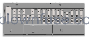
Power Distribution Box
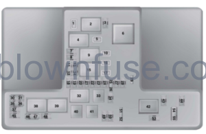
| Fuse Or Relay Number | Fuse Amp Rating | Protected Components |
|---|---|---|
| 1 | 25A 1 | RH front wiper motor. |
| 2 | — | Starter relay. |
| 3 | 15A 2 | Autowipers (rain sensor). Rear wipers. |
| 4 | — | Blower motor relay. |
| 5 | 20A 1 | Back of console auxiliary power point. |
| 6 | — | Auxiliary heater relay. |
| 7 | 20A 2 | Powertrain control module. |
| 8 | 20A 2 | Powertrain control module. |
| 9 | — | Powertrain control module relay. |
| 10 | 20A 1 | Driver front auxiliary power point. |
| 11 | 15A 3 | Powertrain control module. |
| 12 | 15A 3 | Powertrain control module. |
| 13 | 10A 3 | Powertrain control module. |
| 14 | 10A 3 | Powertrain control module. |
| 15 | — | Run-start relay. |
| 16 | 20A 1 | Console auxiliary power point. |
| 17 | 20A 1 | Trunk auxiliary power point (wagon only). |
| 18 | 10A 2 | Powertrain control module. |
| 19 | 10A 2 | Power steering. |
| 20 | 10A 2 | Headlamps. Headlamp switch. |
| 21 | 15A 2 | Transmission control module. Transmission oil pump. |
| 22 | 10A 2 | Air conditioning. |
| 23 | 15A 2 | Blind spot monitor. Rear view camera. Adaptive Cruise Control. Pre-collision warning indicator. Voltage quality module. Air quality sensor. |
| 24 | 10A 2 | Not used (spare). |
| 25 | 10A 3 | Anti-lock brake system. |
| 26 | 10A 3 | Powertrain control module. |
| 27 | — | Not used. |
| 28 | 10A 2 | Rear washer pump. |
| 29 | — | Not used. |
| 30 | — | Not used. |
| 31 | — | Not used. |
| 32 | — | Cooling fan relay. |
| 33 | — | Air conditioning relay. |
| 34 | 15A 2 | Electric steering column lock. |
| 35 | — | Not used. |
| 36 | — | Not used. |
| 37 | — | Not used. |
| 38 | — | Cooling fan relay. |
| 39 | — | Cooling fan relay. |
| 40 | — | Not used. |
| 41 | — | Horn relay. |
| 42 | — | Fuel pump relay. |
| 43 | — | Not used. |
| 44 | 5A 2 | Heated washer nozzle. |
| 45 | — | Not used. |
| 46 | 10A 3 | Alternator. |
| 47 | 10A 3 | Brake on-off switch. |
| 48 | 20A 2 | Horn. |
| 49 | 5A 2 | Mass air flow monitor. |
| 20A 2 | Fuel heater element-Diesel. | |
| 50 | 10A 2 | Power transfer unit cooling fan. |
| 51 | — | Not used. |
| 52 | — | Not used. |
| 53 | 10A 2 | Power seats. |
| 54 | 5A 3 | Fuel operated heater remote control. |
| 55 | 5A 3 | Not used (spare). |
1M-type fuse.2Micro fuse.3Dual micro fuse.Power Distribution Box – BottomThere are fuses located on the bottom of the fuse box. To reach the bottom of the fuse box:
Power Distribution Box – Bottom
There are fuses located on the bottom of the fuse box. To reach the bottom of the fuse box:
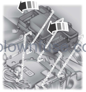
- Release the two latches, located on both sides of the fuse box.
- Raise the inboard side of the fuse box from the cradle.
- Move the fuse box toward the center of the engine compartment.
- Pivot the outboard side of the fuse box to reach the bottom side.
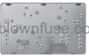
| Fuse Or Relay Number | Fuse Amp Rating | Protected Component |
|---|---|---|
| 56 | — | Not used. |
| 57 | 20A 4 | Diesel vaporizer. |
| 58 | 30A 4 | Fuel pump. |
| 59 | 30A 5 | Cooling fan. |
| 40A 5 | Cooling fan (DW10F and 2.0L GTDI AU). | |
| 60 | 30A 5 | Cooling fan. |
| 40A 5 | Cooling fan (DW10F and 2.0L GTDI AU). | |
| 61 | 40A 4 | Left-hand heated windshield element. |
| 62 | 50A 5 | Body control module. |
| 63 | 25A 4 | Cooling fan. |
| 30A 4 | Cooling fan (DW10F and 2.0L GTDI AU). | |
| 64 | 30A 4 | Auxiliary heater. |
| 65 | 20A 4 | Front heated seat. |
| 66 | 40A 4 | Right-hand heated windshield element. |
| 67 | 50A 5 | Body control module. |
| 68 | 40A 4 | Heated rear window. |
| 69 | 30A 4 | Anti-lock brake system. |
| 70 | 30A 4 | Passenger seat. |
| 71 | 60A 5 | Auxiliary heater. |
| 72 | 30A 4 | Moonroof. |
| 73 | 20A 4 | Rear heated seat. |
| 74 | 30A 4 | Driver seat module. |
| 75 | 30A 4 | Auxiliary heater. |
| 76 | 20A 4 | Transmission oil pump. |
| 77 | 30A 4 | Climate control seat module. |
| 78 | 40A 4 | Trailer tow module. |
| 79 | 40A 4 | Blower motor. |
| 80 | 30A 4 | Power luggage compartment module. |
| 81 | 40A 4 | 220 volt inverter. |
| 82 | 60A 5 | Anti-lock brake system pump. |
| 83 | 25A 4 | RH front wiper motor. |
| 84 | 30A 4 | Starter solenoid. |
| 85 | 20A 4 | Fuel fire heater. |
4M-type fuse.5J-type fuse.
Passenger Compartment Fuse Panel
| Fuse or Relay Number | Fuse Amp Rating | Protected Components |
|---|---|---|
| 1 | — | Not used. |
| 2 | 7.5A 6 | Memory seat. Driver seat lower back support. Panoramic power sunshade (5-door only). |
| 3 | 20A 6 | Driver door unlock. Fuel flap unlock. |
| 4 | 5A 6 | Not used (spare). |
| 5 | 20A 6 | Not used (spare). |
| 6 | 10A 7 | Not used (spare). |
| 7 | 10A 7 | Not used (spare). |
| 8 | 10A 7 | Anti-theft alarm horn. |
| 9 | 10A 7 | Not used (spare). |
| 10 | 5A 7 | Power liftgate module. |
| Telematics control unit. | ||
| 11 | 5A 7 | Combined security module. |
| 12 | 7.5A 7 | Front control integration module (climate and radio control). |
| 13 | 7.5A 7 | Steering wheel column. Instrument cluster. Data link connector. |
| 14 | 10A 7 | Not used (spare). |
| 15 | 10A 7 | Data link gateway. |
| 16 | 15A 6 | Child lock. Luggage compartment-liftglass release. |
| 17 | 5A 7 | Battery backed-up sounder. |
| 18 | 5A 7 | Ignition switch. Push button ignition switch. |
| 19 | 7.5A 7 | Passenger airbag deactivation indicator. |
| 20 | 7.5A 7 | Headlamp control module. |
| 21 | 5A 7 | Passenger compartment thermometer. Humidity sensor. |
| 22 | 5A 7 | Not used (spare). |
| 23 | 10A 6 | Delayed accessory power. |
| 24 | 20A 6 | Lock-unlock. |
| 25 | 30A 6 | Driver door window. Driver door mirror. |
| 26 | 30A 6 | Front passenger door window. Front passenger door mirror. |
| 27 | 30A 6 | Moonroof. |
| 28 | 20A 6 | Audio amplifier. |
| 29 | 30A 6 | Rear driver side door window. |
| 30 | 30A 6 | Rear passenger side door window. |
| 31 | 15A 6 | Not used (spare). |
| 32 | 10A 6 | Global positioning system module. Voice control (SYNC). Information and entertainment display. Radio frequency receiver. |
| 33 | 20A 6 | Radio. |
| 34 | 30A 6 | Run/start bus (fuse #19, 20, 21, 22, 35, 36, 37, circuit breaker). |
| 35 | 5A 6 | Restraints control module. |
| 36 | 15A 6 | Auto-dimming interior mirror. Rear heated seat module. CCD module. Lane keeping system. Auto high beam. |
| 37 | 15A 6 | All wheel drive module. Heated steering wheel. |
| 38 | 30A6 | Not used (spare). |
6Micro fuse.7Dual micro fuse.
CHANGING A FUSE
Fuses
 WARNING: Always replace a fuse with one that has the specified amperage rating. Using a fuse with a higher amperage rating can cause severe wire damage and could start a fire. WARNING: Always replace a fuse with one that has the specified amperage rating. Using a fuse with a higher amperage rating can cause severe wire damage and could start a fire. |
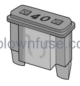
If electrical components in the vehicle are not working, a fuse may have blown. Blown fuses are identified by a broken wire within the fuse. Check the appropriate fuses before replacing any electrical components
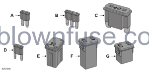
Fuse Types
| Callout | Fuse Type |
|---|---|
| A | Micro 2 |
| B | Micro 3 |
| C | Maxi |
| D | Mini |
| E | M Case |
| F | J Case |
| G | J Case Low Profile |
To download the user manual, please download the following file: