
FUSE SPECIFICATION CHART
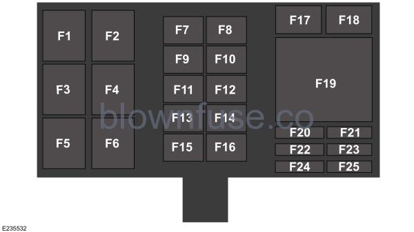
Front Power Distribution Box
 WARNING: Always disconnect the battery before servicing high current fuses. WARNING: To reduce risk of electrical shock, always replace the cover to the power distribution box before reconnecting the battery or refilling fluid reservoirs. WARNING: Always disconnect the battery before servicing high current fuses. WARNING: To reduce risk of electrical shock, always replace the cover to the power distribution box before reconnecting the battery or refilling fluid reservoirs. |
The front power distribution box is under the front hood. See Under Hood Overview. It has high-current fuses that protect your vehicle’s main electrical systems from overloads. There are also high-current fuses next to the front power distribution box. If you need to replace these high-current fuses, see an authorized dealer.If you disconnect and reconnect the battery, you need to reset some features. See Changing the 12V Battery.
| Fuse or Relay Number | Fuse Rating | Protected Components |
|---|---|---|
| F1 | — | Vehicle dynamics module relay. |
| F2 | — | Radiator fan 1 relay. |
| F3 | — | Heating ventilation and air conditioning blower relay. |
| F4 | — | Wipers relay. |
| F5 | — | Radiator fan 2 relay. |
| F6 | — | Horn relay. |
| F7 | 50 A1 | Body control module. |
| F8 | — | Shunt. |
| F9 | 40 A1 | Vacuum pump. |
| F10 | 25 A1 | Wiper. |
| F11 | 40 A1 | Radiator fan 2. |
| F12 | 50 A1 | Body control module. |
| F13 | 60 A1 | Body control module. |
| F14 | 40 A1 | Radiator fan 1. |
| F15 | 40 A1 | Heating ventilation and air conditioning blower. |
| F16 | 40 A1 | Anti-lock brake system. |
| F17 | 40 A1 | Anti-lock brake system. |
| F18 | 30 A1 | Body control module. |
| F19 | — | Vacuum pump relay. |
| F20 | 5 A2 | Vehicle dynamics module. |
| F21 | 20 A2 | Left-hand headlamp. |
| F22 | 5 A2 | Anti-lock brake system. |
| F23 | 20 A2 | Horn. |
| F24 | 20 A2 | Electronic door system. |
| F25 | 20 A2 | Right-hand headlamp. |
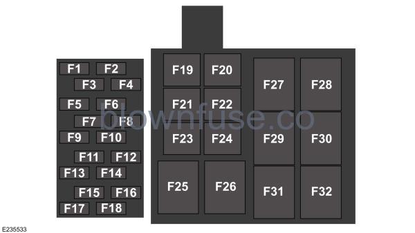
1J-case fuse.2Mini fuse.Rear Power Distribution Box 1The rear power distribution box is in the engine compartment. See Under Hood Overview. It has high-current fuses that protect your vehicle’s main electrical systems from overloads. These are in the right-hand side of the engine compartment behind an access door in the engine surround panel. If you need to replace these high-current fuses, see an authorized dealer.If you disconnect and reconnect the battery, you need to reset some features. See Changing the 12V Battery.
| Fuse or Relay Number | Fuse Rating | Protected Components |
|---|---|---|
| F1 | 15 A3 | Vehicle power 3. |
| F2 | 5 A3 | Mass airflow. |
| F3 | 10 A3 | Engine control module. |
| F4 | 5 A3 | Transmission control module. |
| F5 | 20 A3 | Vehicle power 1. |
| F6 | 5 A3 | Keep alive power. |
| F7 | — | Not used. |
| F8 | 5 A3 | Rear video camera. |
| F9 | — | Not used. |
| F10 | 10 A3 | Alternator sense. |
| F11 | 10 A3 | Air conditioner. |
| F12 | 10 A3 | Damper. |
| F13 | 20 A3 | Vehicle power 4. |
| F14 | — | Not used. |
| F15 | — | Not used. |
| F16 | 5 A3 | Engine control module. Run/start. |
| F17 | 20 A3 | Vehicle power 2. |
| F18 | 15 A3 | Injector. |
| F19 | 30 A45 | Fuel pump 1. |
| F20 | 30 A45 | Fuel pump 2. |
| F21 | 30 A45 | Transmission control module. |
| F22 | 30 A45 | Starter. |
| F23 | 30 A45 | Charge air cooler fan. |
| F24 | — | Shunt. |
| F25 | — | Charge air cooler fan relay. |
| F26 | — | Not used. |
| F27 | — | Fuel pump 1 relay. |
| F28 | — | A/C clutch relay. |
| F29 | — | Starter relay. |
| F30 | — | Fuel injection relay. |
| F31 | — | Fuel pump 2 relay. |
| F32 | — | Engine control module relay. |
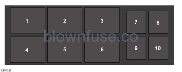
3Mini fuse.4J-case fuse.Rear Power Distribution Box 2The rear power distribution box is in the engine compartment. See Under Hood Overview. It has high-current fuses that protect your vehicle’s main electrical systems from overloads. These are in the right-hand side of the engine compartment behind an access door in the engine surround panel. If you need to replace these high-current fuses, see an authorized dealer.If you disconnect and reconnect the battery, you need to reset some features. See Changing the 12V Battery.
| Fuse or Relay Number | Fuse Rating | Protected Components |
|---|---|---|
| 1 | — | Transmission gear fluid cooler fan relay. |
| 2 | — | Engine oil cooler fan relay. |
| 3 | — | Transmission clutch fluid cooler fan relay. |
| 4 | — | Not used. |
| 5 | — | Not used. |
| 6 | — | Not used. |
| 7 | 20 A45 | Engine oil cooler fan. |
| 8 | 25 A45 | Transmission clutch fluid cooler fan. |
| 9 | 20 A45 | Transmission gear fluid cooler fan. |
| 10 | 20 A45 | Trunk power point. |
5J-case fuse.
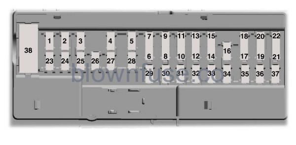
Passenger Compartment Fuse Panel
The fuse panel is in the passenger footwell behind the toeboard panel.

To remove the toeboard panel, rotate each of the four fasteners, and then pull the toeboard panel toward you. Once you remove this panel, you can access the fuse panel. After replacing a fuse, reinstall the toeboard panel and rotate the fasteners back to their original position.
| Fuse or Relay Number | Fuse Rating | Protected Components |
|---|---|---|
| 1 | — | Not used. |
| 2 | 7.5 A6 | Not used (spare). |
| 3 | 20 A6 | Driver unlock relay. Double lock relay. |
| 4 | 5 A6 | Not used (spare). |
| 5 | 20 A6 | Not used (spare). |
| 6 | 10 A7 | Not used (spare). |
| 7 | 10 A7 | Not used (spare). |
| 8 | 10 A7 | Not used (spare). |
| 9 | 10 A7 | Brake on-off switch. |
| 10 | 5 A7 | Push button start switch. |
| 11 | 5 A7 | Right-hand and left-hand exterior door locks and handles. |
| 12 | 7.5 A7 | RF transceiver module. |
| 13 | 7.5 A7 | Steering column control module logic. Smart datalink connector logic. Instrument cluster. |
| 14 | 10 A7 | Extended power mode module. |
| 15 | 10 A7 | Smart datalink connector power. |
| 16 | 15 A6 | Decklid release relay. |
| 17 | 5 A7 | Combined sensor module. |
| 18 | 5 A7 | Telematics control unit – modem. |
| 19 | 7.5 A7 | Not used (spare). |
| 20 | 7.5 A7 | Front damper controllers. |
| 21 | 5 A7 | Shift indicator module head up display. Interior temperature sensor. |
| 22 | 5 A7 | Extended power mode module. |
| 23 | 10 A6 | Right-hand window switch illumination. Right-hand door lock switch illumination. Left-hand door lock switch illumination. Power mirror/window switch (motor). Right-hand smart window motor (logic). Left-hand smart window motor (logic). |
| 24 | 20 A6 | Central lock relay. Central unlock relay. |
| 25 | 30 A6 | Left-hand smart window motor. |
| 26 | 30 A6 | Right-hand smart window motor. |
| 27 | 30 A6 | Not used (spare). |
| 28 | 20 A6 | Electronic steering column lock (relay supply). |
| 29 | 30 A6 | Not used (spare). |
| 30 | 30 A6 | Not used (spare). |
| 31 | 15 A6 | Not used (spare). |
| 32 | 10 A6 | SYNC. Audio on/off switch. Gear shift module. Heating ventilation and air conditioning electronic control unit power. |
| 33 | 20 A6 | Audio control module. |
| 34 | 30 A6 | Run-start relay (R12). |
| 35 | 5 A6 | Steering angle sensor module. |
| 36 | 15 A6 | Auxiliary power point. |
| 37 | 20 A6 | Heating ventilation and air conditioning electronic control unit ignition. Front power distribution box ignition (F1, F3, F20, F22). Rear power distribution box 1 ignition (F4, F8, F12, F16). |
| 38 | — | Not used. |
6Micro 2 fuse.
7Micro 3 fuse.
Note: Spare fuses can vary per amperage depending on the trim level of the vehicle.
2020 Ford GT Owner’s Manual
CHANGING A FUSE
Fuses
| WARNING: Always replace a fuse with one that has the specified amperage rating. Using a fuse with a higher amperage rating can cause severe wire damage and could start a fire. |
If electrical components in the vehicle are not working, a fuse may have blown. Blown fuses are identified by a broken wire within the fuse. Check the appropriate fuses before replacing any electrical components.
Fuse Types

| Callout | Fuse Type |
|---|---|
| A | Micro 2 |
| B | Micro 3 |
| C | Maxi |
| D | Mini |
| E | M Case |
| F | J Case |
| G | J Case Low Profile |