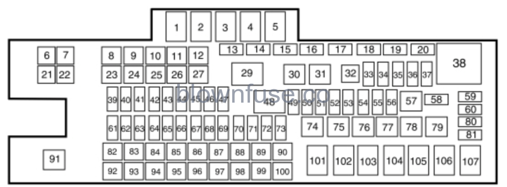
Power Distribution Box
 WARNING: Always disconnect the battery before servicing high current fuses. WARNING: To reduce risk of electrical shock, always replace the cover to the power distribution box before reconnecting the battery or refilling fluid reservoirs. WARNING: Always disconnect the battery before servicing high current fuses. WARNING: To reduce risk of electrical shock, always replace the cover to the power distribution box before reconnecting the battery or refilling fluid reservoirs. |
The power distribution box is located in the engine compartment. It has high-current fuses that protect your vehicle’s main electrical systems from overloads.If you disconnect and reconnect the battery, you will need to reset some features.
| Fuse or relay number | Fuse amp rating | Protected components |
|---|---|---|
| 1 | Relay | Blower motor. |
| 2 | Relay | Trailer tow and body builder stoplamps. |
| 3 | Relay | Urea heaters (diesel engine). |
| 4 | Relay | Driver air ride seat compressor. |
| 5 | Relay | Heated mirrors. |
| 6 | — | Not used. |
| 7 | — | Not used. |
| 8 | 20A* | Passenger air ride seat compressor. |
| 9 | — | Not used. |
| 10 | — | Not used. |
| 11 | — | Not used. |
| 12 | — | Not used. |
| 13 | Resistor | Terminating resistor (120 ohm). |
| 14 | — | Not used. |
| 15 | — | Not used. |
| 16 | — | Not used. |
| 17 | — | Not used. |
| 18 | — | Not used. |
| 19 | 10A* | Brake on/off isolation relay. |
| 20 | — | Not used. |
| 21 | — | Not used. |
| 22 | 30A* | Trailer tow electric brake controller. |
| 23 | 40A* | Blower motor. |
| 24 | — | Not used. |
| 25 | 30A* | Wipers. |
| 26 | 30A* | Trailer tow park lamps. |
| 27 | 25A* | Urea heaters (diesel engine). |
| 28 | — | Not used. |
| 29 | Relay | Trailer tow park lamps. |
| 30 | Relay | A/C clutch. |
| 31 | Relay | Wipers. |
| 32 | — | Not used. |
| 33 | 20A** | Vehicle power 1. |
| 34 | 20A** | Vehicle power 2. |
| 35 | 10A** | Vehicle power 3. |
| 36 | 20A** | Vehicle power 4. |
| 37 | 10A** | Vehicle power 5 (diesel engine). |
| 38 | Relay | Powertrain control module. |
| 39 | — | Not used. |
| 40 | 15A** | Heated mirrors. |
| 41 | — | Not used |
| 42 | 20A** | Trailer tow and body builder stoplamps. |
| 43 | — | Not used. |
| 44 | 20A** | Ancillary translator module. |
| 45 | 10A** | Run/start relay coil. |
| 46 | 10A** | Transmission control module keep-alive power (diesel engine). |
| 47 | 10A** | A/C clutch. |
| 48 | Relay | Run/start. |
| 49 | 20A** | Air dryer. |
| 50 | 10A** | Blower motor relay coil. |
| 51 | — | Not used. |
| 52 | 10A** | Powertrain control module run/start (diesel engine). Transmission control module run/start (diesel engine). |
| 53 | — | Not used. |
| 54 | 10A** | Anti-lock brake system run/start. |
| 55 | 10A** | Seat compressor relay coil. Chassis solenoids relay coil. Heated mirror relay coil. |
| 56 | 20A** | Passenger compartment fuse panel run/start feed |
| 57 | Relay | Fuel pump. |
| 58 | 5A** | Wiper relay. |
| 59 | 5A** | Chassis solenoid relay. Air ride seat compressor relay. |
| 60 | — | Not used. |
| 61 | — | Not used. |
| 62 | — | Not used. |
| 63 | 10A** | Chassis solenoids. |
| 64 | — | Not used. |
| 65 | 10A** | Cargo box lamp. |
| 66 | 30A** | Fuel pump. |
| 67 | — | Not used. |
| 68 | 10A** | Fuel pump relay coil. |
| 69 | — | Not used. |
| 70 | 10A** | Trailer tow or body builder backup lamps. |
| 71 | — | Not used. |
| 72 | 10A** | Powertrain control module relay coil. Keep-alive power. |
| 73 | 5A** | Hydromax monitor. |
| 74 | Relay | Chassis solenoids. |
| 75 | — | Not used. |
| 76 | — | Not used. |
| 77 | Relay | Brake switch isolation (hydraulic brakes). |
| 78 | — | Not used. |
| 79 | — | Not used. |
| 80 | — | Not used. |
| 81 | — | Not used. |
| 82 | 20A* | Auxiliary power point #2. |
| 83 | 20A* | Auxiliary power point #1. |
| 84 | 20A* | Driver air ride seat compressor. |
| 85 | 60A* | Hydromax pump. |
| 86 | 30A* | Anti-lock brake system modulator valves. |
| 87 | — | Not used. |
| 88 | — | Not used. |
| 89 | 40A* | Starter motor |
| 90 | 30A* | Trailer battery feed (air brakes). Trailer tow battery charge (hydraulic brakes). |
| 91 | Relay | Cargo box lamp. |
| 92 | — | Not used. |
| 93 | — | Not used. |
| 94 | 25A* | Upfitter relay #1. |
| 95 | 25A* | Upfitter relay #2. |
| 96 | 60A* | Anti-lock brake system pump (hydraulic brakes). |
| 97 | — | Not used. |
| 98 | — | Not used. |
| 99 | 40A* | Instrument panel 110v power inverter. |
| 100 | 30A* | Trailer tow turn lamp relays. |
| 101 | Relay | Starter. |
| 102 | Relay | Trailer tow battery charge relay (hydraulic brakes). Trailer tow battery feed (air brakes). |
| 103 | Relay | Trailer tow right hand side turn and stop lamps. |
| 104 | Relay | Trailer tow left hand side turn and stop lamps. |
| 105 | — | Not used. |
| 106 | Relay | Trailer tow backup lamps relay. |
| 107 | Relay | Passenger air ride seat compressor relay. |
*J case fuses.**Mini fuses.
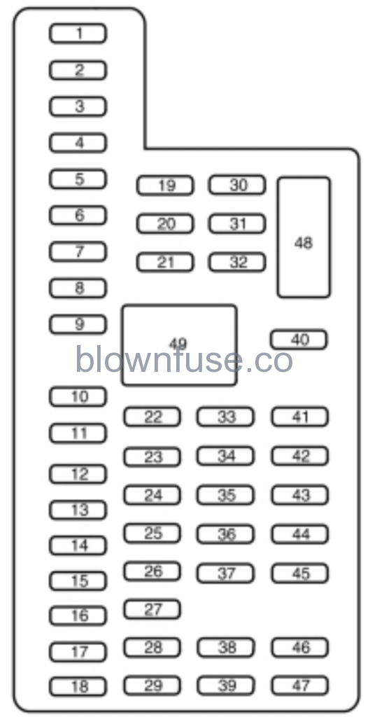
Passenger Compartment Fuse Panel
The fuse panel is in the passenger footwell. Remove the panel cover to access the fuses.Pull the fuse panel cover toward you to remove it. When the clips of the panel disengage, let the panel fall easily.Use the provided fuse puller tool to remove a fuse. It is on the fuse panel cover.
| Fuse or relay number | Fuse amp rating | Protected components |
|---|---|---|
| 1 | 30A | Left front window motor. |
| 2 | 15A | Upfitter relay #4. |
| 3 | 30A | Right front window motor. |
| 4 | 10A | Interior lamps. |
| 5 | — | Not used. |
| 6 | — | Not used. |
| 7 | 7.5A | Power mirror switch. |
| 8 | — | Not used. |
| 9 | 10A | Upfitter relay #3. |
| 10 | 10A | Run/accessory customer access. |
| 11 | 10A | Ford telematics battery feed. |
| 12 | 15A | Interior lighting. |
| 13 | 15A | Right turn and brake lamps. |
| 14 | 15A | Left turn and brake lamps. |
| 15 | 15A | Center high-mounted stop lamp. Backup lamps. |
| 16 | 10A | Right headlamp low beam. |
| 17 | 10A | Left headlamp low beam. |
| 18 | 10A | Powertrain control module wakeup. Brake shift interlock. |
| 19 | — | Not used. |
| 20 | 20A | Power door locks. |
| 21 | 10A | Brake on/off switch. |
| 22 | 20A | Horn. |
| 23 | 15A | Instrument cluster. |
| 24 | 15A | Diagnostic connector. Power fold mirror relay. Steering wheel control module. Remote keyless entry. |
| 25 | — | Not used. |
| 26 | 5A | Steering wheel control module. |
| 27 | — | Not used. |
| 28 | 15A | Ignition switch. |
| 29 | 20A | GPS module. Radio. SYNC. |
| 30 | 15A | Parking lamps. Trailer tow parking lamps relay coil. |
| 31 | 5A | Customer access trailer brake on/off switch. |
| 32 | 15A | Delayed accessory power. Driver and passenger door lock switch illumination. 110v power inverter module. Telescoping mirror switch. |
| 33 | — | Not used. |
| 34 | 10A | Ancillary translator module run/start. |
| 35 | 5A | Tow/Haul run/start. |
| 36 | 10A | Fuel tank select switch. |
| 37 | 10A | Auxiliary heater. |
| 38 | 10A | Delayed accessory power. AM/FM base radio. |
| 39 | 15A | Left and right headlamp high beam. |
| 40 | 10A | Rear parking lamps. Clearance lamps. |
| 41 | — | Not used. |
| 42 | 5A | Ford telematics run/start. |
| 43 | 10A | Power Distribution Box run/accessory fuses. Wiper relay coil. |
| 44 | 10A | Customer access upfitter switch power. Ancillary translator module run/accessory sense. |
| 45 | — | Not used. |
| 46 | 10A | Climate control module. |
| 47 | 15A | Fender direction indicator lamps. |
| 48 | 30A Circuit breaker | Power windows switch (crew cab). |
| 49 | Relay | Delayed accessory power. |
2016 Ford F-650/F-750 Owners Manual
Changing a Fuse
Fuses
| WARNING: Always replace a fuse with one that has the specified amperage rating. Using a fuse with a higher amperage rating can cause severe wire damage and could start a fire. |

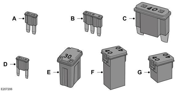
| Callout | Fuse Type |
|---|---|
| A | Micro 2 |
| B | Micro 3 |
| C | Maxi |
| D | Mini |
| E | M Case |
| F | J Case |
| G | J Case Low Profile |