FUSE SPECIFICATION CHART
Power Distribution Box
 WARNING: Always disconnect the battery before servicing high current fuses. WARNING: To reduce risk of electrical shock, always replace the cover to the power distribution box before reconnecting the battery or refilling fluid reservoirs. WARNING: Always disconnect the battery before servicing high current fuses. WARNING: To reduce risk of electrical shock, always replace the cover to the power distribution box before reconnecting the battery or refilling fluid reservoirs. |
Locate the power distribution box in the engine compartment. It has high-current fuses that protect your vehicle’s main electrical systems from overloads.If the battery has been disconnected and reconnected, you will need to reset some features. See Changing the 12V Battery.

| Fuse or relay number | Fuse amp rating | Protected components |
|---|---|---|
| 1 | 5A* | Power brake assist module – Hydromax. |
| 2 | 10A* | Air conditioning compressor clutch. |
| 3 | 20A* | Air conditioning clutch relay coil. Catalyst monitor sensor. Engine heated exhaust gas oxygen sensor #11 and #21. Mass air flow sensor with intake air temperature. Vapor management valve. |
| 4 | 5A* | Powertrain control module memory. Powertrain control module relay coil. |
| 5 | 20A* | Powertrain control module power. |
| 6 | 20A* | Instrument panel dimmer module. Instrument panel fuse #41. Park lamp feeds. Trailer tow running lamp relay coil. |
| 7 | 20A* | Ignition coils. Radio capacitors. |
| 8 | 30A* | Hydromax – Anti-lock brake system module. |
| 9 | 10A* | Powertrain control module. Starter ground relay coil. Starter main relay coil. |
| 10 | 20A* | Daytime running lamps. |
| 11 | 20A* | Fuel pump relay coil. Powertrain control module power. |
| 12 | 25A* | Instrument panel – backup lamp feed. Trailer tow back-up lamps feed. |
| 13 | 30A** | Trailer tow electric brake controller feed. |
| 14 | 60A** | Instrument panel battery feed (fuse #9, 15, 21). Lighting primary fuse. |
| 15 | 20A** | Trailer tow park lamps. |
| 16 | 60A** | Anti-lock brake system module – Hydromax. |
| 40A** | Anti-lock brake system module – Hydroboost. | |
| 17 | 20A** | Horn feed. |
| 18 | 20A** | Backup lamp feed. Tow/haul switch. Transmission control indicator light. |
| 19 | — | Not used. |
| 20 | 30A** | Powertrain control module relay coil. Powertrain control module relay (Power distribution box fuses # 3, 5, 7, 18). |
| 21 | 20A** | Fuel injectors. Fuel pump motor. |
| 22 | 20A** | Cigar lighter feed. Diagnostic tool connector. |
| 23 | 40A** | Blower motor feed. |
| 24 | 50A** | Instrument panel battery feed (fuses #4, 10, 16, 22). |
| 25 | 40A** | Ignition switch feed (Instrument panel fuses #1, 5, 7, 11, 13, 14, 17, 19, 23; Power distribution box fuses #9, 11). |
| 26 | 40A** | Ignition switch feed (Instrument panel fuses #5, 11, 17, 23, 26, 38). |
| 27 | 30A** | Multi-function switch (headlamps). |
| 28 | 30A** | Starter solenoid. |
| 29 | 60A** | Power brake assist motor – Hydromax. |
| 40A** | Anti-lock brake system module – Hydroboost. | |
| R1 | — | Air conditioning clutch relay. |
| R2 | — | Fuel pump relay. |
| R3 | — | Horn relay. |
| R4 | — | Starter relay. |
| R5 | — | Blower motor relay. |
| R6 | — | Powertrain control module relay. |
| Diode 1 | — | Fuel pump diode. |
| Diode 2 | — | Air conditioning clutch diode. |
*Mini fuses.**Maxi fuses.UPS Power Distribution Box 1

| Fuse or relay number | Fuse amp rating | Protected components |
|---|---|---|
| R1 | Relay | Powertrain control module. |
| R2 | Relay | Daytime running lamps. |
| R3 | Relay | Starter motor. |
| R4 | Relay | Blower motor. |
| R5 | Relay | Horn. |
| R6 | Relay | Fuel pump. |
| R7 | Relay | Starter ground. |
| R8 | Relay | Trailer tow parking lamps. |
| R9 | Relay | Back-up lamps. |
| R10 | Relay | Not used. |
| R11 | Relay | Not used. |
| R12 | Relay | Air conditioning. |
| M1-1 | 10A | Hydromax brake on/off relay. |
| M1-2 | — | Not used. |
| M1-3 | — | Not used. |
| M1-4 | — | Not used. |
UPS Power Distribution Box 2

| Fuse or relay number | Fuse amp rating | Protected components |
|---|---|---|
| M1 | 25A* | Back-up lamps. |
| M2 | 20A* | Daytime running lamps. |
| M3 | 30A* | 4–channel anti-lock brake system module (Hydromax). |
| M4 | 20A* | Powertrain control module run/start. Fuel pump relay coil. |
| M5 | 10A* | Starter relay coil. |
| M6 | 20A* | Vehicle power 4. |
| M7 | 5A* | Hydromax motor monitor. |
| M8 | 20A* | Vehicle power 2. |
| M9 | 20A* | Vehicle power 1. |
| M10 | 10A* | Air conditioning. |
| M11 | 5A* | Powertrain control module relay keep alive power. |
| M12 | 20A* | Parking lamps. |
| D1 | Diode | One-touch start. |
| D2 | Diode | Fuel pump. |
| D3 | Diode | Air conditioning. |
| R2-1 | — | Not used. |
| J1 | 30A** | Powertrain control module vehicle power. |
| J2 | 20A** | Fuel pump. |
| J3 | 20A** | Cigar lighter power point. Diagnostic connector. |
| J4 | 40A** | Blower motor. |
| J5 | 30A** | Headlamps. |
| J6 | 40A** | Ignition switch feeds. |
| J7 | 40A** | Ignition switch feeds. |
| J8 | 50A** | Instrument panel fuse box. |
| J9 | 30A** | Starter motor solenoid. |
| J10 | 40A** | 3–channel anti-lock brake system module. |
| 60A** | 4–channel anti-lock brake system module (Hydromax). | |
| J11 | 30A** | Trailer tow electronic brake. |
| J12 | 60A** | Lighting. |
| J13 | 20A** | Vehicle power 3. |
| J14 | 20A** | Horn. |
| J15 | 40A** | 3–channel anti-lock brake system module. |
| 60A** | 4–channel anti-lock brake system module. | |
| J16 | 20A** | Trailer tow parking lamps. |
*Mini fuse.**J-case fuse.Diode and Relay ModuleLocate the module box with the power distribution box in from of the radiator.

| Relay location | Protected components |
|---|---|
| 1 | One-touch integrated start (ATO diode). |
| 2 | Not used. |
| 3 | Not used. |
| 4 | Daytime running lamps power relay. |
| 5 | Hydromax – brake on/off signal isolating relay. |
| 6 | Reverse lamps relay. |
| 7 | Starter ground relay. |
| 8 | Trailer tow parking lamps relay. |
Fuse Holder ModuleLocate the fuse holder next to the diode and relay module.
| Fuse number | Fuse amp rating | Protected components |
|---|---|---|
| 1 | 10A | Hydromax – brake on/off signal. |
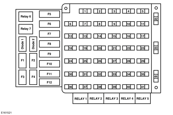
Passenger Compartment Fuse PanelLocate this fuse panel below and to the left of the steering wheel near the brake pedal. Remove the panel cover to access the fuses.To remove a fuse, use the fuse panel cover’s fuse puller tool.
| Fuse or relay number | Fuse amp rating | Protected components |
|---|---|---|
| 1 | 20A | Body builder rear direction indicator and stop lamp feeds. Direction indicators. Direction indicators and stop lamps. |
| 2 | — | Not used. |
| 3 | — | Not used. |
| 4 | 10A | Instrument cluster. |
| 5 | 10A | Body builder accessory feed (accessory and run). |
| 6 | — | Not used. |
| 7 | 15A | Blower motor relay coil. |
| 8 | 10A | Brake lamps feed. |
| 9 | 20A | Stop lamps: Vehicle direction indicators and stop lamps, Body builder rear direction indicators and stop feeds, Body builder stop lamp feed. |
| 10 | 10A | Instrument cluster memory. |
| 11 | 30A | Wiper/washer module. Wiper feed. |
| 12 | — | Not used. |
| 13 | 10A | Anti-lock brake system module – Hydromax. |
| 14 | 10A | Anti-lock brake system module – Hydroboost. Instrument cluster power. Instrument cluster warning lamps. Warning indicator module. |
| 15 | 15A | Left-hand direction indicator feed. |
| 16 | 20A | Body builder battery (+12V) feed. |
| 17 | 5A | Body builder radio feed. |
| 18 | — | Not used. |
| 19 | 5A | Daytime running lamps relays. |
| 20 | — | Not used. |
| 21 | 15A | Right-hand direction indicator feed. |
| 22 | 20A | Trailer tow direction indicators. |
| 23 | 10A | Cluster run/accessory. |
| 24 | — | Not used. |
| 25 | 10A | Body builder right-hand low beam headlamp feed. |
| 26 | 10A | Brake shift interlock actuator. |
| 27 | — | Not used. |
| 28 | — | Not used. |
| 29 | — | Not used. |
| 30 | — | Not used. |
| 31 | 10A | Body builder left-hand low beam headlamp feed. |
| 32 | — | Not used. |
| 33 | 10A | Reverse lamps. |
| 34 | 10A | Body builder reverse gear. Trailer tow reverse lamps. |
| 35 | 20A | Body builder high beam feed. High beam indicator. |
| 36 | — | Not used. |
| 37 | — | Not used. |
| 38 | 10A | Body builder run feed. |
| 39 | — | Not used. |
| 40 | — | Not used. |
| 41 | 10A | Instrument cluster lighting. |
| 42 | — | Not used. |
| 43 | — | Not used. |
| 44 | — | Not used. |
| Relay 1 | — | Trailer tow right-hand direction indicator. |
| Relay 2 | — | Trailer tow left-hand direction indicator. |
| Relay 3 | — | Right-hand direction indicator. |
| Relay 4 | — | Left-hand direction indicator. |
| Relay 5 | — | Not used. |
| Relay 6 | — | Daytime running lamps. Parking brake. |
| Relay 7 | — | Daytime running lamps on/off. |
| Diode 1 | — | Brake transmission shift interlock. |
| Diode 2 | — | Brake transmission shift interlock. |
| F1 | — | Not used. |
| F2 | — | Not used. |
| F3 | — | Not used. |
| F4 | 10A | Brake transmission shift interlock. |
| F5 | — | Not used. |
| F6 | — | Not used. |
| F7 | — | Not used. |
| F8 | — | Not used. |
| F9 | — | Not used. |
| F10 | — | Not used. |
| F11 | — | Not used. |
| F12 | — | Not used. |
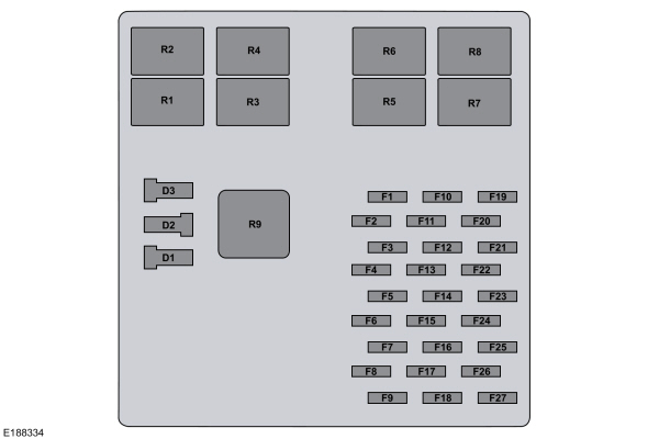
UPS Passenger Compartment Fuse Panel
| Fuse or relay number | Fuse amp rating | Protected components |
|---|---|---|
| F1 | 20A | Body builder battery (+12V) feed. |
| F2 | 20A | Flasher run. |
| F3 | 15A | Left turn. |
| F4 | 15A | Blower relay coil. |
| F5 | 15A | Right turn. |
| F6 | 10A | ABS run. |
| F7 | 10A | Body builder headlamp. |
| F8 | 5A | Daytime running lamps. |
| F9 | 10A | Body builder headlamp. |
| F10 | — | Not used. |
| F11 | 10A | Cluster battery (+12V) #1. |
| F12 | 5A | UPS BTSI. |
| F13 | 10A | Cluster battery (+12V) #2. |
| F14 | 10A | Switch illumination. |
| F15 | 20A | Body builder battery (+12V) feed. |
| F16 | — | Not used. |
| F17 | 20A | Trailer tow run. |
| F18 | 10A | Body builder run. |
| F19 | 10A | Brake lamp feed. |
| F20 | 10A | Body builder run. |
| F21 | 10A | R/S. |
| F22 | 30A | Wiper module battery (+12V). |
| F23 | 10A | Reverse lamps. |
| F24 | 5A | Body builder radio. |
| F25 | 10A | Trailer tow reverse lamps. |
| F26 | 10A | Cluster R/S. |
| F27 | 20A | Daytime running lamps. |
| R1 | — | Daytime running lamps. Parking brake. |
| R2 | — | Daytime running lamps on/off. |
| R3 | — | Right-hand direction indicator. |
| R4 | — | Trailer tow right-hand direction indicator. |
| R5 | — | Left-hand direction indicator. |
| R6 | — | Trailer tow left-hand direction indicator. |
| R7 | — | Not used. |
| R8 | — | Not used. |
| R9 | — | Not used. |
| D1 | — | Not used. |
| D2 | — | Not used. |
| D3 | — | Not used. |
CHANGING A FUSE
Fuses
| WARNING: Always replace a fuse with one that has the specified amperage rating. Using a fuse with a higher amperage rating can cause severe wire damage and could start a fire. |

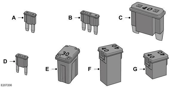
| Callout | Fuse Type |
|---|---|
| A | Micro 2 |
| B | Micro 3 |
| C | Maxi |
| D | Mini |
| E | M Case |
| F | J Case |
| G | J Case Low Profile |
To download the complete user manual, please download the following file: