
FUSE SPECIFICATION CHART
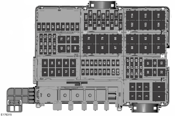
Power Distribution Box
 WARNING: Always disconnect the battery before servicing high current fuses. WARNING: To reduce risk of electrical shock, always replace the cover to the power distribution box before reconnecting the battery or refilling fluid reservoirs. WARNING: Always disconnect the battery before servicing high current fuses. WARNING: To reduce risk of electrical shock, always replace the cover to the power distribution box before reconnecting the battery or refilling fluid reservoirs. |
The power distribution box is located in the engine compartment. It has high-current fuses that protect your vehicle’s main electrical systems from overloads.If you disconnect and reconnect the battery, you will need to reset some features. See Changing the 12V Battery.
| Fuse or relay number | Fuse amp rating | Protected components |
|---|---|---|
| 1 | — | Not used. |
| 2 | — | Not used. |
| 3 | — | Not used. |
| 4 | — | Telescoping side-view mirror. |
| 5 | 40A* | Rear window defroster. |
| 6 | — | Not used. |
| 7 | — | Not used. |
| 8 | — | Telescoping side-view mirror. |
| 9 | 30A* | Fuel pump. |
| 10 | 40A* | Charge air cooler fans (Raptor only). |
| 11 | 60A* | Automatic brake system motor. |
| 12 | 50A* | Body control module 1. |
| 13 | 60A* | Body control module 2. |
| 14 | 20A** | Amplifier. |
| 15 | 25A** | 4×4. |
| 16 | 10A** | Spot light module. |
| 17 | 15A** | Heated seat. |
| 18 | 10A** | Steering-column lock. |
| 19 | 10A** | Power seats. |
| 20 | 15A** | Snow plow. Rear heated seats. |
| 21A | 15A** | Transmission control module. |
| 21B | — | Not used. |
| 22 | 30A* | Windshield wiper motor. |
| 23 | 15A* | Rain sensor. |
| 24 | 25A* | Series fan feed. |
| 25 | — | Not used. |
| 26 | 30A* | Driver seat motors. |
| 27 | 30A* | Passenger power seat. |
| 28 | 30A* | Climate controlled seat. |
| 29 | 25A* | Upfitter fuses 94, 96, 98 and 100 (Raptor only). |
| 30 | — | Air conditioner clutch relay. |
| 31 | — | Not used. |
| 32 | — | Not used. |
| 33 | 50A* | Electric fan 3. |
| 34 | 25A* | Trailer tow park lamps. |
| 35 | 20A* | Trailer tow stop-turn relay fuse. |
| 36 | 25A* | Trailer tow lamps module. |
| 37 | 50A* | Electric fan 1. |
| 38 | 10A** | Alt A sensor. |
| 39 | 10A** | Integrated wheel end solenoid. |
| 40 | 15A** | E-locker. |
| 41 | 10A** | Telescoping mirror. |
| 42 | 30A** | Transmission fluid pump. |
| 43 | 25A** | Horn. |
| 44 | 10A** | Air conditioner clutch. |
| 45 | 10A** | Powertrain control module relay coil. |
| 46 | 10A** | Wiper relay coil. |
| 47 | 15A* | Upfitter 1 (Raptor only). |
| 48 | 15A* | Upfitter 2 (Raptor only). |
| 49 | 30A* | Trailer brake control module. |
| 50 | 30A* | Power running boards. |
| 51 | — | Fuel pump relay. |
| 52 | — | Not used. |
| 53 | — | Upfitter 5 relay (Raptor only). |
| 54 | 30A* | Voltage quality module. Body-control-module voltage-quality-module feed. |
| 55 | 40A* | Body control module RP2 feed. |
| 56 | 20A* | Fuel pump. |
| 57 | 30A* | Right-hand electric parking brake actuator. |
| 58 | 30A* | Left-hand electric parking brake actuator. |
| 59 | 30A* | Starter. |
| 60 | 40A* | Blower motor. |
| 61 | 30A* | Brake control module. Automatic brake system valves. |
| 62 | — | Power seat relay. |
| 63 | 15A** | Heated mirrors. |
| 64 | — | Upfitter 6 relay (Raptor only). |
| 65 | — | Starter relay. |
| 66 | — | Powertrain control module relay. |
| 67 | — | Windshield wiper relay. |
| 68 | — | Blower motor relay. |
| 69 | — | Power sliding back window relay. |
| 70 | — | Electric fan 1 relay. |
| 71 | — | Not used. |
| 72 | 25A* | 4×4. |
| 73 | — | Not used. |
| 74 | 30A* | PDRG motor. |
| 75 | — | Horn relay. |
| 76 | — | Not used. |
| 77 | — | Steering column lock relay. |
| 78 | — | Not used. |
| 79 | — | Trailer tow parking lamp relay. |
| 80 | — | Rear window defroster relay. |
| 81 | — | Upfitter 1 relay (Raptor only). |
| 82 | — | PDRG close relay. |
| 83 | — | Upfitter 2 relay (Raptor only). |
| 84 | — | Not used. |
| 85 | — | Not used. |
| 86 | — | Not used. |
| 87 | 10A** | Trailer tow backup lamps. |
| 88 | — | Not used. |
| 89 | 20A* | Cigar lighter power point 1. |
| 90 | 20A* | Power point 2. |
| 91 | 20A* | Power point 3. |
| 92 | 20A* | Power point 4. |
| 93 | 25A** | GTDI vehicle power 1. |
| 10A** | PFI vehicle power 1. | |
| 94 | 10A** | Upfitter 3 (Raptor only). |
| 95 | 25A** | Vehicle power 2. |
| 96 | 10A** | Upfitter 4 (Raptor only). |
| 97 | 10A** | Vehicle power 3. |
| 98 | 5A** | Upfitter 5 (Raptor only). |
| 99 | 20A** | Vehicle power 4 (PFI). |
| 15A** | Vehicle power 4 (GTDI). | |
| 100 | 5A** | Upfitter 6 (Raptor only). |
| 101 | — | Not used. |
| 102 | — | Snow plow relay. |
| 103 | — | Charge air cooler fan (Raptor only). |
| 104 | — | Electronic fan 3 relay. |
| 105 | 10A** | Power steering. |
| 106 | — | Not used. |
| 107 | 10A** | Anti-lock brakes. |
| 108 | — | Not used. |
| 109 | 10A** | Powertrain control module. Transmission control module run-start power. |
| 110 | 10A** | 4×4 run/start. Adaptive cruise control. |
| 111 | 15A** | Transmission pump run-start. |
| 112 | 10A** | Charge air cooler relay coil run-start (Raptor only). |
| 113 | 7.5A** | Blind spot information system. Rear view camera. Front view camera. Voltage quality module. |
| 114 | — | Electric fan 2 relay. |
| 115 | — | Upfitter 3 relay (Raptor only). |
| 116 | — | Upfitter 4 relay (Raptor only). |
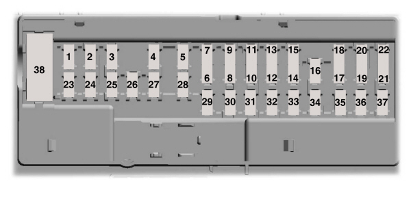
*Cartridge fuses**Mini fusesPassenger Compartment Fuse PanelThe fuse panel is in the right-hand side of the passenger footwell behind a trim panel.To remove the trim panel, pull it toward you and swing it away from the side. To reinstall it, line up the tabs with the grooves on the panel, and then push it shut.To remove the fuse panel cover, press in the tabs on both sides of the cover, and then pull it off.To reinstall the fuse panel cover, place the top part of the cover on the fuse panel and push the bottom part until it latches. Gently pull on the cover to make sure it has latched properly.
| Fuse or relay number | Fuse amp rating | Protected components |
|---|---|---|
| 1 | 10A | Demand lamp relay. Power seats relay. Glove box. Vanity lamps. Overhead console. Dome. Courtesy. Map lamps. |
| 2 | 7.5A | Memory module logic. Memory seat switches. Lumbar motor. |
| 3 | 20A | Driver door lock motor. |
| 4 | 5A | Trailer brake control. |
| 5 | 20A | Not used. |
| 6 | 10A | Not used. |
| 7 | 10A | Not used. |
| 8 | 10A | Not used. |
| 9 | 10A | Not used (spare). |
| 10 | 5A | Embedded modem module. |
| 11 | 5A | Combined sensor module. |
| 12 | 7.5A | Climate head module. Smart datalink converter. |
| 13 | 7.5A | Cluster. SCCM. |
| 14 | 10A | Brake. |
| 15 | 10A | Smart datalink converter. |
| 16 | 15A | Tailgate release. |
| 17 | 5A | HUD. Terrain switch. |
| 18 | 5A | Ignition switch and passive-entry passive-start start stop switch. Key inhibit solenoid. |
| 19 | 7.5A | Tow haul (O/D) cancel for floor or column shifter. |
| 20 | — | Not used. |
| 21 | 5A | HUD. In car temperature with humidity sensor. |
| 22 | 5A | EPB. Power seat. |
| 23 | 10A | PDRG switch. Inverter. Driver side window. Moonroof. Vista roof. |
| 24 | 20A | Central lock/unlock. |
| 25 | 30A | Driver door control module. |
| 26 | 30A | Passenger door control module. |
| 27 | 30A | Vista roof. Moonroof. |
| 28 | 20A | Not used. |
| 29 | 30A | Not used. |
| 30 | 30A | Not used. |
| 31 | 15A | Adjustable pedal switch and motor. |
| 32 | 10A | Multi-function display. Global position system. SYNC. Radio frequency receiver. |
| 33 | 20A | Radio. |
| 34 | 30A | Run-start relay. |
| 35 | 5A | Restraints module. |
| 36 | 15A | 360 camera module. Heated steering wheel module. Rear-view mirror. Rear heated seats. |
| 37 | 20A | Power distribution box run-start fuses. |
| 38 | 30A Circuit breaker. | Rear window switches and motors. |
CHANGING A FUSE
Fuses
| WARNING: Always replace a fuse with one that has the specified amperage rating. Using a fuse with a higher amperage rating can cause severe wire damage and could start a fire. |

If electrical components in the vehicle are not working, a fuse may have blown. Blown fuses are identified by a broken wire within the fuse. Check the appropriate fuses before replacing any electrical components.
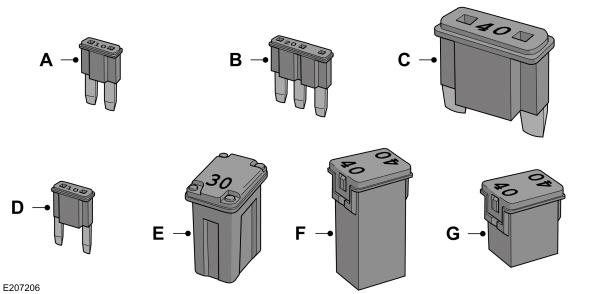
Fuse Types
| Callout | Fuse Type |
|---|---|
| A | Micro 2 |
| B | Micro 3 |
| C | Maxi |
| D | Mini |
| E | M Case |
| F | J Case |
| G | J Case Low Profile |
To download the complete user manual, please download the following file: