
Power Distribution Box
 WARNING: Always disconnect the battery before servicing high-current fuses. WARNING: To reduce risk of electrical shock, always replace the cover to the power distribution box before reconnecting the battery or refilling fluid reservoirs. WARNING: Always disconnect the battery before servicing high-current fuses. WARNING: To reduce risk of electrical shock, always replace the cover to the power distribution box before reconnecting the battery or refilling fluid reservoirs. |
The power distribution box is located in the engine compartment. It has high-current fuses that protect your vehicle’s main electrical systems from overloads.If the battery has been disconnected and reconnected, some features will need to be reset.
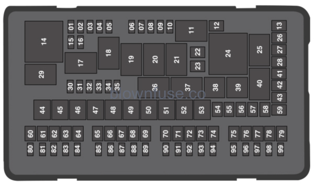
| Fuse or relay number | Fuse amp rating | Protected components |
|---|---|---|
| 1 | 20A1 | Powertrain control module power. |
| 2 | 20A1 | Engine emissions (MIL). |
| 3 | 20A1 | A/C clutch control relay coil. VACC. Active grill shutters. |
| 4 | 20A1 | Ignition coils. |
| 5 | — | Not used. |
| 6 | — | Not used. |
| 7 | — | Not used. |
| 8 | — | Not used. |
| 9 | — | Not used. |
| 10 | 15A1 | Heated mirrors. |
| 11 | — | Right hand side electronic cooling fan 3 relay. |
| 12 | 40A2 | Heated rear window. |
| 13 | — | Not used. |
| 14 | — | Powertrain control module relay. |
| 15 | 20A1 | Horn relay power. |
| 16 | 10A1 | A/C clutch relay power. |
| 17 | — | Rear heated window and heated mirrors relay. |
| 18 | — | Rear blower motor relay. |
| 19 | — | Not used. |
| 20 | — | Left hand side cooling fan relay. |
| 21 | — | Cooling fans series/parallel relay. |
| 22 | 25A2 | Electronic fan relay 2. |
| 23 | — | Not used. |
| 24 | — | Not used. |
| 25 | — | Not used. |
| 26 | 30A2 | Anti-lock brake system valves. |
| 27 | 20A2 | Trailer tow battery charge relay power. |
| 28 | — | Not used. |
| 29 | — | Run/start relay. |
| 30 | — | Not used. |
| 31 | 10A1 | Electric power-assisted steering. |
| 32 | 10A1 | Anti-lock brake system module. |
| 33 | 10A1 | Powertrain control module (ISPR). |
| 34 | 10A1 | Blind spot information system. Adaptive cruise control. Front view camera. Rear camera. |
| 35 | — | Not used. |
| 36 | — | Blower motor relay. |
| 37 | — | Trailer tow battery charge relay. |
| 38 | — | A/C compressor clutch relay. |
| 39 | — | Horn relay. |
| 40 | — | Not used. |
| 41 | 40A2 | Rear blower motor. |
| 42 | — | Not used. |
| 43 | 40A2 | Front blower motor. |
| 44 | 50A3 | Voltage quality module bus. |
| 45 | 40A3 | Electronic fan relay 1. |
| 46 | 30A3 | Trailer tow brake controller. |
| 47 | — | Not used. |
| 48 | 50A3 | Body control module RP1 bus. |
| 49 | — | Not used. |
| 50 | 50A3 | Body control module RP2 bus. |
| 51 | 50A3 | Electronic fan relay 3. |
| 52 | 60A3 | Anti-lock brake system pump. |
| 53 | — | Not used. |
| 54 | — | Not used. |
| 55 | — | Not used. |
| 56 | 40A2 | Power inverter. |
| 57 | — | Not used. |
| 58 | — | Not used. |
| 59 | — | Not used. |
| 60 | 20A2 | Power point (front console bin). |
| 61 | — | Not used. |
| 62 | 20A2 | Power point (instrument panel). |
| 63 | 30A2 | Fuel pump. |
| 64 | — | Not used. |
| 65 | 20A2 | Power point (2nd row) (without USB charger). |
| 66 | — | Not used. |
| 67 | 20A2 | Power point (cargo area). |
| 68 | — | Not used. |
| 69 | 30A2 | Power liftgate. |
| 70 | 15A2 | Trailer tow left-hand and right-hand stop and direction indicator lamps. |
| 71 | — | Not used. |
| 72 | 30A2 | Heated/cooled seats. |
| 73 | 30A2 | Driver seat module. Driver seat power. |
| 74 | 30A2 | Passenger seat power. |
| 75 | 30A2 | Front wiper motor. |
| 76 | — | Not used. |
| 77 | — | Not used. |
| 78 | 30A2 | 3rd row power folding seat module relay. |
| 79 | 30A2 | Starter relay. |
| 80 | — | Not used. |
| 81 | 10A1 | Trailer tow back-up lamp relay. |
| 82 | — | Not used. |
| 83 | 10A1 | Brake on/off switch. |
| 84 | — | Not used. |
| 85 | 5A1 | 2nd row USB charger (if equipped). |
| 86 | — | Not used. |
| 87 | — | Not used. |
| 88 | — | Not used. |
| 89 | — | Not used. |
| 90 | — | Not used. |
| 91 | — | Not used. |
| 92 | 15A1 | Multi-contour seat module relay. |
| 93 | 10A1 | Alternator sense. |
| 94 | 15A1 | Rear washer relay. |
| 95 | 15A1 | Rear wiper relay. |
| 96 | 10A1 | Powertrain control module relay coil power. |
| 97 | 5A1 | Rain sensor. |
| 98 | 20A1 | 2nd row seat motors. |
| 99 | 20A1 | Trailer tow parking lamp relay. |
1Micro fuse.2M-type fuse.3J-type fuse.
Passenger Compartment Fuse Panel
The fuse panel is located under the instrument panel to the left of the steering column.Note: It may be easier to access the fuse panel if you remove the finish trim piece.
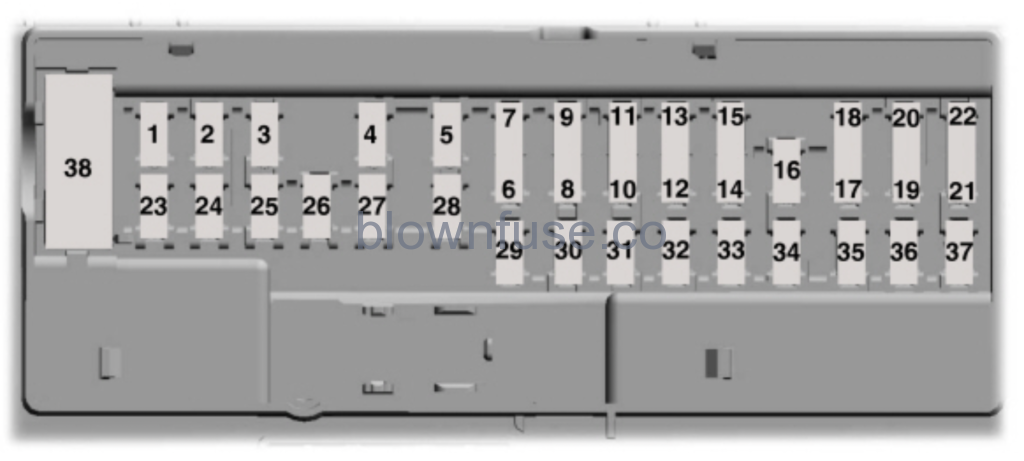
| Fuse or relay number | Fuse amp rating | Protected components |
|---|---|---|
| 1 | 10A1 | Demand lamps. Battery saver. |
| 2 | 7.5A1 | Memory seat switch (lumbar power). |
| 3 | 20A1 | Driver unlock relay. |
| 4 | 5A1 | Aftermarket electronic brake controller. |
| 5 | 20A1 | Rear heated seat module. |
| 6 | — | Not used. |
| 7 | — | Not used. |
| 8 | — | Not used. |
| 9 | — | Not used. |
| 10 | 5A2 | Securicode™ keyless entry keypad. Hands free liftgate. |
| 11 | 5A2 | Rear climate control module. |
| 12 | 7.5A2 | Front climate control module. |
| 13 | 7.5A2 | Instrument cluster. Smart data link. Steering column control module. |
| 14 | — | Not used. |
| 15 | 10A2 | Smart datalink connector power. Heads up display. |
| 16 | — | Not used. |
| 17 | 5A2 | Electronic finish panel. |
| 18 | 5A2 | Push button start switch. Ignition switch. Key inhibit. |
| 19 | 7.5A2 | Transmission control switch (tow haul). |
| 20 | — | Not used. |
| 21 | 5A2 | Terrain management switch. Heads up display. Humidity sensor. |
| 22 | 5A2 | Occupant classification sensor. |
| 23 | 10A1 | Delayed accessory power. Power windows. Moonroof. Folding mirror relay. DC inverter. Window/moonroof switch illumination. |
| 24 | 20A1 | Central lock relay. |
| 25 | 30A1 | Left-hand front smart window motor. Door zone module. |
| 26 | 30A1 | Right-hand front smart window motor. Door zone module. |
| 27 | 30A1 | Moonroof. |
| 28 | 20A1 | Sony amplifier – 10 channel. |
| 29 | 30A1 | Sony amplifier – 14 channel. |
| 30 | — | Not used. |
| 31 | — | Not used. |
| 32 | 10A1 | SYNC. GPS module. Display. Radio frequency receiver. |
| 33 | 20A1 | Radio. |
| 34 | 30A1 | Run/start relay. |
| 35 | 5A1 | Restrain control module. |
| 36 | 15A1 | Lane departure warning module. Auto high beam. EC mirrors. Rear heated seats. |
| 37 | 20A1 | Heated steering wheel. |
| 38 | 30A 3 | Left-hand front window motor. Rear power window motors. |
1Micro fuse.2Dual micro fuse.3Circuit breaker.
2016 Ford Explorer Owners Manual
Changing a Fuse
Fuses
| WARNING: Always replace a fuse with one that has the specified amperage rating. Using a fuse with a higher amperage rating can cause severe wire damage and could start a fire. |

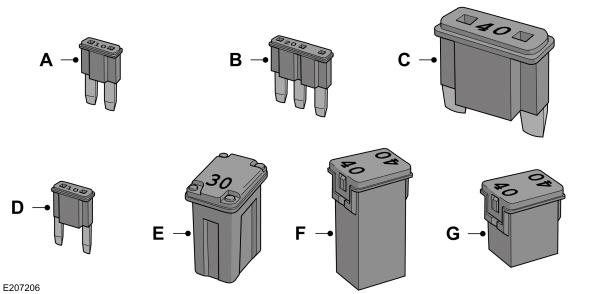
| Callout | Fuse Type |
|---|---|
| A | Micro 2 |
| B | Micro 3 |
| C | Maxi |
| D | Mini |
| E | M Case |
| F | J Case |
| G | J Case Low Profile |