
FUSE SPECIFICATION CHART
Power Distribution Box
 WARNING: Always disconnect the battery before servicing high current fuses. WARNING: To reduce risk of electrical shock, always replace the cover to the power distribution box before reconnecting the battery or refilling fluid reservoirs. WARNING: Always disconnect the battery before servicing high current fuses. WARNING: To reduce risk of electrical shock, always replace the cover to the power distribution box before reconnecting the battery or refilling fluid reservoirs. |
Note: If your vehicle is equipped with dual batteries, disconnecting the primary under-hood battery does not remove power from all circuits.The power distribution box is located in the engine compartment. It has high-current fuses that protect your vehicle’s main electrical systems from overloads.If the battery has been disconnected and reconnected, you will need to reset some features. See Changing the 12V Battery.
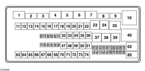
| Fuse or relay number | Fuse amp rating | Protected components |
|---|---|---|
| 1 | — | Powertrain control module relay. |
| 2 | — | Starter solenoid relay. |
| 3 | — | Wiper relay. |
| 4 | — | Trailer tow battery charge. |
| 5 | — | Fuel pump relay. |
| 6 | — | Trailer tow park lamp relay. |
| 7 | — | Auxiliary switch #4 relay. |
| 8 | — | Auxiliary switch #3 relay. |
| 9 | — | Modified vehicle and stripped chassis run/start relay. |
| 10 | — | Cooling fan relay (6.2L engine). |
| 11 | 50A*** | Cooling fan (6.2L engine). |
| 12 | 40A** | Modified vehicle and stripped chassis run/start. |
| 13 | 30A** | Starter solenoid relay. |
| 14 | 40A** | Run/start relay. |
| 15 | 40A** | Modified vehicle and stripped chassis battery. |
| 16 | 50A** | Auxiliary air conditioning blower. |
| 17 | 50A** | Trailer tow battery charge. Trailer tow park feed. |
| 18 | 30A** | Electric trailer brake. Trailer brake controller. |
| 19 | 30A** | Auxiliary switch #1. |
| 20 | 30A** | Auxiliary switch #2. |
| 21 | — | Not used. |
| 22 | — | Not used. |
| 23 | — | Air conditioning clutch relay. |
| 24 | — | Horn relay (stripped chassis). |
| 25 | — | Run/start relay. |
| 26 | 10* | Alternator battery sense (6.2L engine). |
| 27 | — | Not used. |
| 28 | 20A* | Back-up lamp. |
| 29 | 10A* | Air conditioning clutch. |
| 30 | 10A* | Brake on/off switch. |
| 31 | 10A* | Cluster battery (stripped chassis). |
| 32 | 50A** | Blower motor. |
| 33 | 40A** | Anti-lock brake system pump. |
| 34 | 20A** | Stripped chassis horn. |
| 35 | 40A** | Powertrain control module relay. |
| 36 | 20A** | Ignition switch (stripped chassis). |
| 37 | — | Trailer tow left-hand side stop lamp and direction indicator lamp relay. |
| 38 | — | Trailer tow right-hand side stop lamp and direction indicator lamp relay. |
| 39 | — | Back-up lamp relay. |
| 40 | — | Blower motor relay. |
| 41 | — | Not used. |
| 42 | 15A* | Diagnostic connector (stripped chassis). |
| 43 | 20A* | Fuel pump. |
| 44 | 10A* | Auxiliary switch #3. |
| 45 | 15A* | Auxiliary switch #4. |
| 46 | 10A* | Powertrain control module keep alive memory power. Canister vent control valve. Powertrain control module relay coil. |
| 47 | 40A** | Anti-lock brake system relay coil. |
| 48 | 20A** | Trailer tow stop lamp and direction indicator lamps. |
| 49 | 30A** | Wiper motor. |
| 50 | — | Not used. |
| 51 | 20A** | Cutaway. |
| 52 | 10A* | Modified vehicle and stripped chassis run/start relay coil. |
| 53 | 10A* | Anti-lock brake system run/start feed. |
| 54 | 10A* | Fuel pump relay coil. |
| 55 | — | Not used. |
| 56 | — | Not used. |
| 57 | 20A* | Trailer tow park lamp. |
| 58 | 15A* | Trailer tow back-up lamp. |
| 59 | — | Not used. |
| 60 | — | One-touch integrated start diode. |
| 61 | — | Not used. |
| 62 | — | Auxiliary switch #2 relay. |
| 63 | 30A** | Trailer tow battery charge. |
| 64 | — | Not used. |
| 65 | 20A** | Power point 2 (glove box). |
| 66 | 20A** | Power point 3 (cutaway B+). |
| 67 | 20A** | Power point 1 (instrument panel). |
| 68 | 50A** | Modified vehicle. |
| 69 | — | Not used. |
| 70 | 30A** | Stripped chassis. |
| 71 | — | Not used. |
| 72 | 20A** | Cigarette lighter/power point. |
| 73 | — | Not used. |
| 74 | 30A** | Power seat. |
| 75 | 20A* | Vehicle power 1. Powertrain control module power. |
| 76 | 20A* | Vehicle power 2. Powertrain control module emissions related components. |
| 77 | 10A* | Vehicle power 3. Powertrain control module general components. |
| 78 | 15A* | Vehicle power 4. Engine ignition coil relay coil. |
| 79 | 10A* | Vehicle power 5. Transmission. |
| 80 | 10A* | Cluster run/start (stripped chassis). |
| 81 | — | Not used. |
| 82 | — | Not used. |
| 83 | — | Fuel pump diode. |
| 84 | — | Not used. |
| 85 | — | Auxiliary switch #1 relay. |
*Mini fuses.**A1S fuses.***Cartridge fuses.Passenger Compartment Fuse Panel
| WARNING: Always disconnect the battery before servicing high current fuses. |
Note: If your vehicle is equipped with dual batteries, disconnecting the primary under-hood battery does not remove power from all circuits.The fuse panel is located to the left of the brake pedal and mounted onto the lower left cowl panel. Remove the fuse panel cover to access the fuses.To remove a fuse, use the fuse puller tool provided on the inside of the fuse panel cover.
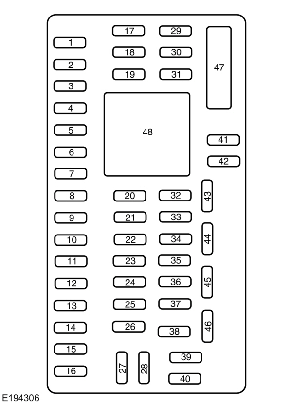
| Fuse or relay number | Fuse amp rating | Protected components |
|---|---|---|
| 1 | 30A | Inverter B+. |
| 2 | 15A | Not used (spare). |
| 3 | 15A | Not used (spare). |
| 4 | 30A | Not used (spare). |
| 5 | 10A | Passenger compartment fuse panel. Brake-shift interlock. |
| 6 | 20A | Direction indicators lamps. Hazard lamps. Stop lamps. |
| 7 | 10A | Left-side headlamp low beam. |
| 8 | 10A | Right-side headlamp low beam. |
| 9 | 15A | Courtesy lamps. |
| 10 | 15A | Switch illumination. |
| 11 | 10A | Not used (spare). |
| 12 | 7.5A | Not used (spare). |
| 13 | 5A | Mirrors. |
| 14 | 10A | SYNC. Global positioning system module. |
| 15 | 10A | Not used (spare). |
| 16 | 15A | Not used (spare). |
| 17 | 20A | Door locks. |
| 18 | 20A | Not used (spare). |
| 19 | 25A | Not used (spare). |
| 20 | 15A | Diagnostic connector (except stripped chassis). |
| 21 | 15A | Not used (spare). |
| 22 | 15A | Parking lamps. License plate lamps. |
| 23 | 15A | Headlamp high beams. |
| 24 | 20A | Horn (except stripped chassis). |
| 25 | 10A | Demand lighting. |
| 26 | 10A | Cluster (except stripped chassis). |
| 27 | 20A | Ignition switch feed. |
| 28 | 5A | Audio mute (start). |
| 29 | 5A | Cluster (except stripped chassis). |
| 30 | 5A | Not used (spare). |
| 31 | 10A | Not used (spare). |
| 32 | 10A | Restraints module. |
| 33 | 10A | Trailer brake controller. |
| 34 | 5A | Not used (spare). |
| 35 | 10A | Cutaway run/start. |
| 36 | 5A | Passive anti-theft system radio frequency module. |
| 37 | 10A | Climate control. Stripped chassis #1 run/start. |
| 38 | 20A | Not used (spare). |
| 39 | 20A | Radio. |
| 40 | 20A | Not used (spare). |
| 41 | 15A | Radio. Switch illumination. Automatic dimming rear view mirror. Power inverter. |
| 42 | 10A | Auxiliary switch. |
| 43 | 10A | Stripped chassis instrument panel connector #1. |
| 44 | 10A | Trailer tow battery charge relay. |
| 45 | 5A | Wipers. Stripped chassis engine connector 3. |
| 46 | 7.5A | Passenger airbag deactivation indicator. |
| 47 | 30A | Windows accessory delay circuit breaker. |
| 48 | — | Delayed accessory relay. |
CHANGING A FUSE
Fuses
| WARNING: Always replace a fuse with one that has the specified amperage rating. Using a fuse with a higher amperage rating can cause severe wire damage and could start a fire. |

If electrical components in the vehicle are not working, a fuse may have blown. Blown fuses are identified by a broken wire within the fuse. Check the appropriate fuses before replacing any electrical components.
Fuse Types
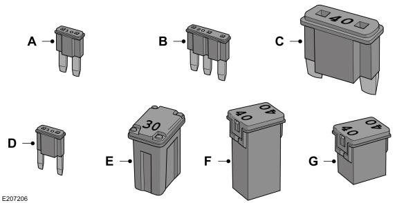
| Callout | Fuse Type |
|---|---|
| A | Micro 2 |
| B | Micro 3 |
| C | Maxi |
| D | Mini |
| E | M Case |
| F | J Case |
| G | J Case Low Profile |
To download the complete user manual, please download the following file: