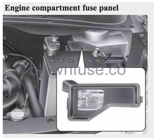
Below is the engine compartment fuse diagram for the Hyundai i10 2007, 2008, 2009, 2010, 2011, 2012, and 2013 model year. The fuse panel is under the hood and behind the battery. It is has a rectangular shape and is made of black plastic. Inside the fuse/relay panel covers, you can find the fuse/relay label describing the fuse/relay name and capacity.

| Fuse Code | AMP | Description |
|---|---|---|
| MAIN | 100A (Gasoline) / 125A (Diesel) | Engine room box B+, Alternator |
| MDPS | 80A | MDPS_B |
| IGN 2 | 50A | Key set, Start relay |
| IGN 1 | 30A | Key set |
| BATT1 | 30A | Memory fuse (AUDIO 15A/ ROOM LP 10A), Tail relay |
| ECU | 30A | Main relay, F/PUMP 20A, ECU 2 10A |
| R/FAN | 30A | Radiator fan high relay, Radiator fan low relay |
| F_HTR | 30A | Fuel heater relay (Diesel) |
| BATT2 | 50A | LOCK ROOF 20A, RR HTD 25A, HAZARD 10A, STOP 10A, F/FOG 10A, HORN 10A |
| P/WDW | 30A | I/P box (Power window relay B+) |
| ABS 2 | 40A | ABS unit, ESP unit, Air bleeding |
| ABS 1 | 40A | ABS unit. ESP unit. Air bleeding |
| BLWR | 30A | Blower relay |
| ECU | 10A | ECU, PTC Module (Diesel) |
| INJ | 15A | Injector 1/2/3/4, ISCA, ECU, Glow relay (Diesel), PTC 1/2/3 relay (Diesel), VGT actuator (Diesel), EGR actuator (Diesel), Throttle actuator (Diesel), Vacuum swirl (Diesel), Camshaft position sensor (Diesel), Immobiliser unit |
| SNSR | 10A | ECU, Crankshaft position sensor, Camshaft position sensor, 02 up sensor, 02 down sensor, Immobiliser unit, Lambda sensor (Diesel), Stop switch (Diesel) |
| ECU (DSL) | 20A | ECU (Diesel) |
| F_PUMP | 20A | Fuel pump relay |
| A/CON | 10A | Air conditioner relay |
Below is a video showing the location of the passenger fuse box inside the car.