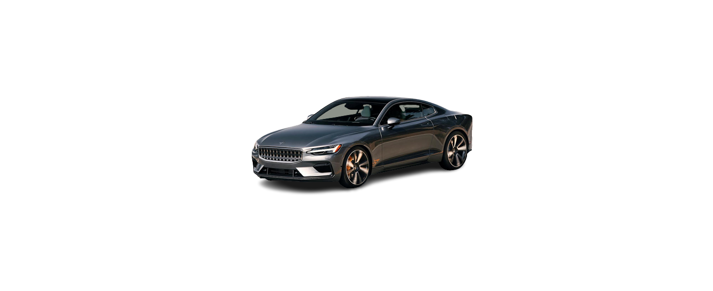
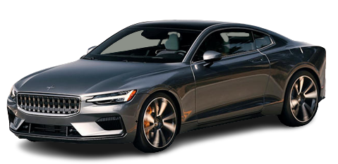
Polestar 1

2021 Polestar 1 Camera and Radar Sensor Owners Manual

2021 Polestar 1 Camera and Radar Sensor

Camera

The camera is used by several driver support systems to e.g. detect lane marker lines or road signs.

Location of the camera

The camera is used by the following functions:

  • Adaptive Cruise Control*
  • Pilot Assist*
  • Lane Keeping Aid
  • Steering assistance at risk of collision
  • City Safety
  • Driver Alert Control
  • Traffic sign information
  • Active high beam
  • Park Assist System

Camera/radar sensor limitations

The camera and radar sensor used by several of the driver support functions has certain limitations, which also affect the functions using the camera and radar sensor. The driver should be aware of the following limitations:

Camera and radar sensor limitations

Obstructed camera
The area marked in the illustration must be cleaned regularly and kept free of decals, objects, solar film, etc. The camera is located on the upper interior section of the windshield along with the radar sensor. Do not place, affix or mount anything on the inside or outside of the windshield, or in front of or around the camera and radar sensor – this could disrupt camera and radar-based functions. It could cause functions to be reduced, deactivated completely or to produce an incorrect function response.

High temperatures

If the temperature in the passenger compartment is very high, the camera/radar sensor will switch off temporarily for approx. 15 minutes after the engine is started to protect its electronic components. When the temperature has cooled sufficiently, the camera/radar sensor will automatically restart.

Damaged windshield

NOTE
Failure to take action could result in reduced performance for the driver support systems that use the camera and radar unit. It could cause functions to be reduced, deactivated completely or to produce an incorrect function response.

To avoid the risk of malfunction of the driver support systems that use the radar sensor, the following also apply:

  • If there are cracks, scratches or stone chips on the windshield in front of any of the camera and radar sensor “windows” and this covers an area of about 0.5×3.0 mm (0.02×0.12 in.) or more, contact Polestar Customer Support to have the windshield replaced.
  • Polestar advises against repairing cracks, scratches or stone chips in the area in front of the camera and radar sensor – the entire windshield should instead be replaced.
  • Before replacing the windshield, contact Polestar Customer Support to verify that the right windshield has been ordered and installed.
  • The same type of windshield wipers or wipers approved by Polestar should be used for replacement.
  • If the windshield is replaced, the camera and radar sensor must be recalibrated by a workshop to help ensure proper functioning of all of the vehicle’s camera and radar-based systems. Contact Polestar Customer Support.

Additional radar limitations

Vehicle speed
The radar sensor’s ability to detect a vehicle ahead is significantly reduced if the speed of the vehicle ahead differs greatly from your vehicle’s speed.

Limited field of vision

The radar sensor has a limited field of vision. In some situations, it may detect a vehicle later than expected or not at all.

The radar sensor’s field of vision

  1. The radar sensor’s detection of vehicles very close to your vehicle may be delayed in certain situations, e.g. if a vehicle pulls in between your vehicle and the vehicle directly ahead.
  2. Small vehicles, such as motorcycles, or vehicles that are not driving in the center of the lane may remain undetected.
  3. In curves, the radar may detect a different vehicle or lose sight of a target vehicle.

Low trailers

Low trailer in the radar shadow Low trailers may also be difficult or even impossible for the radar to detect. The driver should be extra alert when driving behind vehicles towing low trailers when Adaptive Cruise Control or Pilot Assist is activated.

Additional camera limitations

Reduced visibility
Cameras have the same limitations as the human eye. In other words, their “vision” is impaired by adverse weather conditions such as heavy snowfall/rain, dense fog, swirling dust/snow, etc. These conditions may reduce the function of systems that depend on the camera or cause these systems to temporarily stop functioning.
Strong sunlight, reflections from the road surface, ice or snow covering the road, a dirty road surface, or unclear lane marker lines may drastically reduce the camera’s ability to detect the side of a lane, a pedestrian, a cyclist, a large animal or another vehicle.

Additional Park Assist Camera limitations

Blind sectors

There are “blind” sectors between the cameras’ fields of vision. With the Park Assist Camera’s 360° view selected, objects/obstacles may not be detected if they are located in the “joints” where the edges of the individual camera views meet.

WARNING
Even if it seems as though only a fairly small section of the screen image is obstructed, this may mean that a relatively large sector is hidden and an obstacle there may not be detected until it is very near the vehicle.

Lighting conditions

The camera image is automatically adjusted according to the current lighting conditions. This means that the brightness and quality of the image may vary slightly. Poor lighting conditions may result in reduced image quality.

Camera/radar unit symbols and messages

Here are examples of some of the messages and symbols related to the camera and radar unit that may be displayed in the instrument panel.

Sensor blocked

If this symbol and the message Windscreen sensorSensor blocked, see Manual is displayed in the instrument panel, it means that the camera and radar sensor are unable to detect other vehicles, cyclists, pedestrians and large animals in front of the vehicle and that the vehicle’s camera and radar-based functions may be obstructed.

The following table shows some of the situations that can cause the message to be displayed, and suggested actions:

Cause Action
The area of the windshield in front of the camera/radar sensor is dirty or covered by ice or snow. Clean the windshield in front of the camera/radar sensor and remove dirt, ice and snow.
Thick fog, heavy rain or snow is blocking the radar signals or the camera’s range of visibility. No action. Heavy precipitation may sometimes prevent the camera/radar sensor from functioning.
Water or snow is spraying/swirling up and blocking the radar signals or the camera’s range of visibility. No action. Very wet or snow-covered roads may sometimes prevent the camera/radar sensor from functioning.
There is dirt between the inside of the windshield and the camera/radar sensor. The windshield on the inside of the camera casing needs to be cleaned – contact Polestar Customer Support.
Bright sunlight. No action. The camera/radar sensor will reset automatically when lighting conditions improve.

Defective camera

If a camera sector is dark and contains this symbol, this indicates that the camera is not functioning properly.

The vehicle’s left-side camera is malfunctioning.

A dark camera sector may also be displayed in the following situations, but without the defective camera symbol:

  • a door is open
  • the trunk lid is open
  • a rearview mirror is folded in

Radar sensor

The radar sensor is used by several driver support systems to detect other vehicles.
Location of radar sensor

The radar sensor is used by the following functions:

  • Distance Alert*
  • Adaptive Cruise Control*
  • Pilot Assist*
  • Lane Keeping Aid
  • City Safety

Any modifications to the radar sensor may make its use illegal.

Radar sensor type approval

Type approval for the vehicle’s radar sensors for Adaptive Cruise Control* (ACC), Pilot Assist* and BLIS are provided here.
Market ACC & PA BLIS Type approval
Canada

FCC ID: L2C0054TR IC: 3432A-0054TR

FCC ID: L2C0055TR IC: 3432A-0055TR

Canada Standard RSS-310
USA

FCC ID: L2C0054TR IC: 3432A-0054TR

FCC ID: L2C0055TR IC: 3432A-0055TR

FCC ID: NBG01RS4

This device complies with Part 15 of the FCC Rules and with Industry Canada license-exempt RSS standard(s). Operation is subject to the following two conditions:

  1. This device may not cause harmful interference, and
  2. This device must accept any interference received, including interference that may cause undesired operation.

Cet appareil est conforme aux CNR d’Industrie Canada a applicables aux appareils radio exempts de licence. L’exploitation est autorisée à condition que l’appareil ne produise pas de brouillage préjudiciable et qu’il accepte tout brouillage, même celui susceptible d’en compromettre le fonctionnement.

CAUTION TO USERS: Changes or modifications not expressively approved by the party responsible for compliance could void the user’s authority to operate the equipment. The term “IC:” before the radio certification number only signifies that Industry Canada’s technical specifications were met.

Note: This equipment complies with radiation exposure limits set forth for an uncontrolled environment. This equipment should be installed and operated with a  minimum distance of 20 cm between the radiator and your body.

For detailed information on type approval, contact Polestar Customer Support.

Recommended camera and radar sensor maintenance

In order for the camera and radar sensors to function properly, they must be kept free of dirt, ice, snow, etc. and should be washed regularly with water and car washing detergent.
NOTE
Dirt, ice and snow covering the sensors could cause false warnings, reduced function, or no function.
Location of the Park Assist sensors
Location of rear radar sensors. Keep the marked area clean (on both the left and right sides of the vehicle).
  • For best possible performance, it is important to keep the areas in front of the sensors clean.
  • Do not attach any objects, tape or decals to the surface of the sensors.
  • Clean the camera lenses regularly using lukewarm water and car washing detergent. Wash gently to avoid scratching the lens.
IMPORTANT
Only a workshop may perform maintenance on driver support components – contact Polestar Customer Support.
Automotive Solutions

Recent Posts

VW Jetta Engine Fuse Box Diagram

Access the comprehensive 2010-2018 VW Jetta Passenger Fuse Box Diagram to troubleshoot electrical issues effectively.…

7 months ago

VW Jetta Passenger Fuse Box Diagram

Explore the comprehensive VW Jetta Passenger Fuse Box Diagram to troubleshoot electrical issues effectively. Understand…

7 months ago

2023 Ford F-150 Lightning Fuse Box Diagram

Under Hood Fuse Box Location Remove the front luggage compartment cover. Under Hood Fuse Box…

2 years ago

2022 Kawasaki NINJA H2 SX SE Brake Lever Adjuster Owner’s Manual

2022 Kawasaki NINJA H2 SX SE Brake Lever Adjuster Owner's Manual NOTICE Only adjust the front…

2 years ago

2023 Land Rover Range Rover Evoque Exiting The Vehicle Owners Manual

2023 Land Rover Range Rover Evoque Exiting The Vehicle SINGLE LOCKING WARNING Before exiting the…

2 years ago

2023 Land Rover Range Rover Evoque Front Seats Owners Manual

2023 Land Rover Range Rover Evoque Front Seats FRONT SEAT SAFETY Make sure to read…

2 years ago