2023 Land Rover NEW RANGE ROVER FUSES
FUSE BOX LOCATIONS
CAUTION
When a fuse box lid is removed, take care to protect the box from moisture. Refit the lid at the earliest opportunity. Make sure that the fuse box lid is fitted correctly and the clips are secure.
When a fuse box lid is removed, take care to protect the box from moisture. Refit the lid at the earliest opportunity. Make sure that the fuse box lid is fitted correctly and the clips are secure.
NOTES
Only customer-accessible fuses are listed for the engine compartment fuse box.
Only customer-accessible fuses are listed for the engine compartment fuse box.
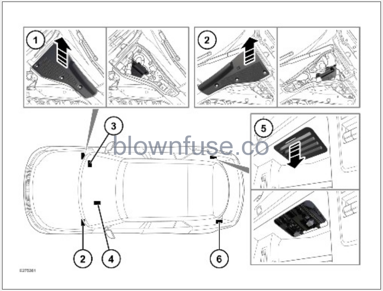
There are six fuse box locations on the vehicle. Each fuse box contains fuses that protect different groups of circuits.
- Engine compartment fuse box – right-hand.
- Engine compartment fuse box – left-hand.
- Passenger compartment fuse box – right-hand.
NOTES
On the right-hand drive vehicles, the fuse box is located in the area above and to the left of the brake pedal. - Passenger compartment fuse box – left-hand.
NOTES
On right-hand drive vehicles, the fuse box is located behind the carpet toward the front, left side of the passenger’s footwell. - Loadspace fuse boxes – right-hand.
- Loadspace fuse box – left-hand.
ENGINE COMPARTMENT FUSE BOXES:
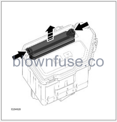
The engine compartment fuse boxes are located under the hood of the vehicle. To access the fuses:
- Remove the under-hood cover. See UNDER-HOOD COVERS REMOVAL.
- Release the 2 clips and remove the cover.
PASSENGER COMPARTMENT FUSE BOX – RIGHT-HAND:
The passenger compartment fuse box is located on the passenger side of the vehicle under the carpet. To access the fuses, open the carpet access flap.
The passenger compartment fuse box is located on the passenger side of the vehicle under the carpet. To access the fuses, open the carpet access flap.
PASSENGER COMPARTMENT FUSE BOX – LEFT-HAND:
The passenger compartment fuse box is located behind a trim panel above the pedals. To access the fuses, remove the trim panel above the pedals.
NOTES
Note the fitted position of the trim panel before releasing the trim panel.
Note the fitted position of the trim panel before releasing the trim panel.
LOADSPACE FUSE BOX – RIGHT-HAND:
The loadspace fuse boxes are located behind an access panel on the right-hand side of the loadspace. To access the fuses, pull on the top edge of the access panel and remove.
The loadspace fuse boxes are located behind an access panel on the right-hand side of the loadspace. To access the fuses, pull on the top edge of the access panel and remove.
LOADSPACE FUSE BOX – LEFT-HAND:
The loadspace fuse box is located behind an access panel on the left-hand side of the loadspace. To access the fuses, carefully remove the trim panel.
The loadspace fuse box is located behind an access panel on the left-hand side of the loadspace. To access the fuses, carefully remove the trim panel.
NOTES
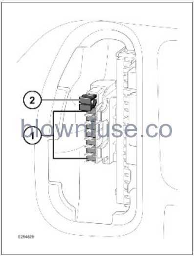
The left-hand loadspace fuse box also contains a number of spare fuses (1) and a fuse removal tool (2). See REPLACING A FUSE.
The left-hand loadspace fuse box also contains a number of spare fuses (1) and a fuse removal tool (2). See REPLACING A FUSE.
REPLACING A FUSE
CAUTION
Always switch off the ignition system and the affected electrical circuit before replacing a fuse. Failure to do so could cause damage to the vehicle.
Always switch off the ignition system and the affected electrical circuit before replacing a fuse. Failure to do so could cause damage to the vehicle.
CAUTION
Fit approved replacement fuses of the same rating and type, or fuses of a matching specification. Using an incorrect fuse may result in damage to the vehicle’s electrical system and can result in a fire.
Fit approved replacement fuses of the same rating and type, or fuses of a matching specification. Using an incorrect fuse may result in damage to the vehicle’s electrical system and can result in a fire.
CAUTION
If the replacement fuse blows after fitment, the system should be checked by a retailer/authorized repairer. Further damage could be caused to the vehicle if ignored.
If the replacement fuse blows after fitment, the system should be checked by a retailer/authorized repairer. Further damage could be caused to the vehicle if ignored.
NOTES
Relays and fuses not detailed in the Owner’s Handbook should only be replaced by qualified persons.
Relays and fuses not detailed in the Owner’s Handbook should only be replaced by qualified persons.
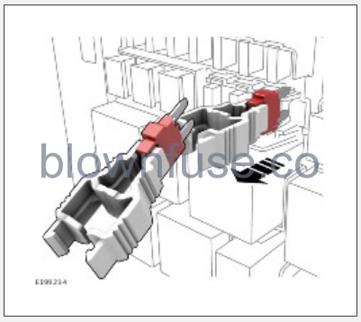
If an electrical system has stopped operating, the cause may be a blown fuse. The easiest way to check if a fuse has blown is to first remove it.
To check for a blown fuse:
- Refer to the fuse box tables shown in this section to identify the correct fuse.
- Gain access to the appropriate fuse box. See FUSE BOX LOCATIONS.
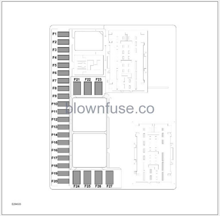
- Refer to the fuse box diagram below to locate the correct fuse.
- Use the fuse removal tool to remove the fuse. See FUSE BOX LOCATIONS.
- Check for a break in the wire within the fuse. If the wire within the fuse is broken, the fuse has blown and needs replacing. If the wire is still intact, consult a retailer/authorized repairer.
- Refit or replace the fuse, as appropriate. Make sure the fuse is pushed fully into its correct position.
Copyright Limited 2022.
ENGINE COMPARTMENT FUSE BOX
FUSE BOX – LEFT-HAND:
| Fuse no. | Rating (amps) | Fuse color | Circuit |
|---|---|---|---|
| 1 | 10 | Red. | Heated washer jet. |
| 2 | 30 | Green. | Windshield wiper motor. |
| 3 | 10 | Red. | Exhaust solenoid valve. |
| 4 | 5 | Tan. | Gasoline cooling system. |
| 5 | – | – | – |
| 6 | 3 | Violet. | Toll module. |
| 7 | 5 | Tan. | Radar sensor – front. |
| 8 | 5 | Tan. | Radar sensor – front corner RH / LH. |
| 9 | 5 | Tan. | Terrain optimisation switch. |
| 10 | 5 | Tan. | Electronic suspension system. |
| 11 | 20 | Yellow. | Driveline module. |
| 12 | – | – | – |
| 13 | 25 | Clear. | Left-side headlight. |
| 14 | – | – | – |
| 15 | – | – | – |
| 16 | 15 | Blue | All Terrain Progress Control (ATPC), gear selector. |
| 17 | 10 | Red. | Driver assistance systems module. |
| 18 | 5 | Tan. | Forward camera. |
| 19 | – | – | – |
| 20 | 5 | Tan. | Engine management system. |
FUSE BOX – RIGHT-HAND:
| Fuse no. | Rating (amps) | Fuse color | Circuit |
|---|---|---|---|
| 1 | 15 | Blue. | Horn. |
| 2 | 25 | White. | Front and rear washer pump. |
| 3 | 5 | Tan. | Engine management systems (V8 engine only). |
| 4 | 25 | White. | Right-side headlight. |
| 5 | – | – | – |
| 6 | – | – | – |
| 7 | 15 | Blue. | Coolant pump. |
| 8 | 5 | Tan. | Engine management systems. |
| 9 | 25 | White. | Forward camera wash. |
| 10 | – | – | – |
| 11 | 25 | White. | Headlight washer. |
| 12 | – | – | – |
| 13 | – | – | – |
| 14 | – | – | – |
| 15 | – | – | – |
| 16 | – | – | – |
| 17 | – | – | – |
| 18 | – | – | – |
| 19 | – | – | – |
| 20 | – | – | – |
RELATED INFORMATION
Copyright Limited 2022.
LOADSPACE FUSE BOX
FRONT FUSE BOX – RIGHT-HAND:
| Fuse no. | Rating (amps) | Fuse color | Circuit |
|---|---|---|---|
| 1 | – | – | – |
| 2 | – | – | – |
| 3 | – | – | – |
| 4 | – | – | – |
| 5 | 30 | Green. | Rear seat module. |
| 6 | – | – | – |
| 7 | 15 | Blue. | Rear wiper. |
| 8 | – | – | – |
| 9 | – | – | – |
| 10 | 10 | Red. | Keyless entry. |
| 11 | – | – | – |
| 12 | – | – | – |
| 13 | – | – | – |
| 14 | 15 | Blue. | Cool box. |
| 15 | 5 | Tan. | Telematics. |
| 16 | 7.5 | Brown. | Rear touchscreen, Fuel Burning Heater (FBH), Tire Pressure Monitoring System (TPMS). |
| 17 | 5 | Tan. | Keyless entry. |
| 18 | 5 | Tan. | Smart module. |
| 19 | – | – | – |
| 20 | – | – | – |
REAR FUSE BOX – RIGHT-HAND:
| Fuse no. | Rating (amps) | Fuse color | Circuit |
|---|---|---|---|
| 1 | – | – | – |
| 2 | 10 | Red. | Chassis control systems. |
| 3 | 15 | Blue. | Chassis control systems. |
| 4 | 15 | Blue. | Rear USB sockets. |
| 5 | 15 | Blue. | Rear portable media. |
| 6 | – | – | – |
| 7 | 5 | Tan. | Phone signal module. |
| 8 | 10 | Red. | 2nd row USB accessory socket. |
| 9 | 20 | Yellow. | Accessory socket loadspace. |
| 10 | 20 | Yellow. | 3rd row USB accessory socket. |
| 11 | 20 | Yellow. | Rear console. |
| 12 | 10 | Red. | Rear seat accessory socket. |
| 13 | 5 | Tan. | Acoustic Domain Controller (ADC). |
| 14 | 15 | Blue. | Right-side tail lights. |
| 15 | 10 | Red. | Right-side tailgate tail lights. Left-side tailgate tail lights. |
| 16 | 5 | Tan. | Climate and comfort systems. |
| 17 | 10 | Red. | Chassis control. |
| 18 | – | – | – |
| 19 | – | – | – |
| 20 | – | – | – |
FUSE BOX – LEFT-HAND:
| Fuse no. | Rating (amps) | Fuse color | Circuit |
|---|---|---|---|
| 1 | 15 | Blue | Trailer socket. |
| 2 | 5 | Tan. | Suspension system. |
| 3 | 15 | Blue. | Trailer socket. |
| 4 | 15 | Blue. | Rear portable media. |
| 5 | 10 | Red. | Driver assistance systems. |
| 6 | – | – | – |
| 7 | 5 | Tan. | Audio systems. |
| 8 | – | – | – |
| 9 | 5 | Tan. | Gesture tailgate. |
| 10 | 5 | Tan. | Audio systems. |
| 11 | 10 | Red. | Electronic suspension systems. |
| 12 | – | – | – |
| 13 | – | – | |
| 14 | 10 | Red. | Rear display. |
| 15 | 15 | Blue. | Left-side tail lights. |
| 16 | 5 | Tan. | Telematics. |
| 17 | – | – | – |
| 18 | – | – | – |
| 19 | – | – | – |
| 20 | – | – | – |
