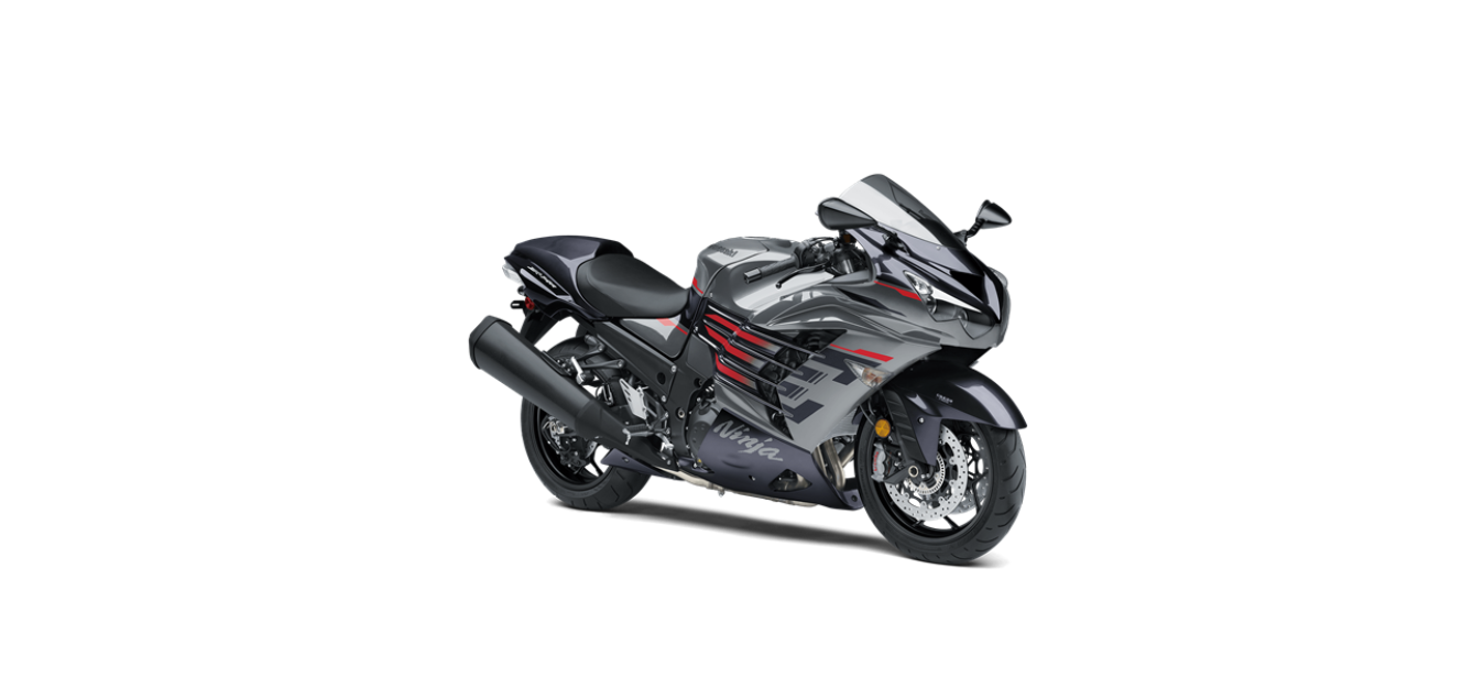
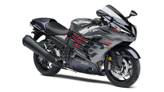
2022 Kawasaki NINJA ZX-14R Battery Owners Manual


2022 Kawasaki NINJA ZX-14R Battery


Battery
The battery installed in this motorcycle is a sealed type, so it is not necessary to check the battery electrolyte level or add distilled water.
NOTICE
Never remove the sealing strip, or the battery can be damaged. Do not install a conventional battery in this motorcycle, or the electrical system cannot work properly.
Battery Maintenance
It is the owner’s responsibility to keep the battery fully charged. Failure to do so can lead to battery failure and leave you stranded. If you are riding your vehicle infrequently, inspect the battery voltage weekly using a voltmeter. If it drops below 12.6 volts, the battery should be charged using an appropriate charger (check with your Kawasaki dealer). If you will not be using the motorcycle for longer than two weeks, the battery should be charged using an appropriate charger. Do not use an automotive-type quick charger that may overcharge the battery and damage it.
NOTE
Leaving the battery connected causes the electrical components (clock etc.) to make the battery discharge, resulting the over-discharge of the battery. In this case, the repair or replacement of the battery is not included in the warranty. If you do not drive for four weeks or more, disconnect the battery from the vehicle.
Kawasaki-recommended chargers are:
- Battery Mate 150-9
- OptiMate 4
- Yuasa MB-2040/2060
- Christie C10122S
If the above chargers are not available, use equivalent one. For more details, ask your Kawasaki dealer.
Battery Charging
- Charge the battery following the instructions of your battery charger.
- The charger will keep the battery fully charged until you are ready to reinstall the battery in the motorcycle (see Battery Installation).
DANGER
- Battery acid generates hydrogen gas which is flammable and explosive under certain conditions. It is present within a battery at all times, even in a discharged condition. Keep all flames and sparks (cigarettes) away from the battery.
- Wear eye protection when working with a battery. In the event of battery acid contact with skin, eyes, or clothing, wash the affected areas immediately with water for at least five minutes. Seek medical at- tention.
WARNING
Battery posts, terminals and related accessories contain lead and lead compounds, chemicals known to the State of California to cause cancer and reproductive harm. Wash hands after handling.
Battery Removal
- Make sure the ignition switch is turned off.
- Remove the bolts and washers.
A. Bolts and Washers
- Pull the right fairing cover outward to clear the projections of the right fairing cover.
- Pull the right fairing cover downward to clear the tabs of the right fairing cover.
A. Right Fairing Cover
B. Projections
C. Tabs
- Pull outward.
- Pull downward.
Remove the right fairing cover from the right inner rubber cover.
A. Right Fairing Cover
B. Right Inner Rubber Cover
Pull the right fairing cover backward to clear the ends of the right fairing cover, and remove it.
A. Right Fairing Cover
B. Ends
- Remove the bolt and washer.
- Pull the battery compartment cover outward to clear the projections of the battery compartment cover.
A. Bolt and Washer
B. Battery Compartment Cover
C. Projections
- Remove the bolt.
- Clear the frame ground lead from the band.
- Remove the bolts and bracket.
A. Bolt
B. Frame Ground Lead
C. Band
D. Bolts
E. Bracket
- Slightly pull out the battery with the battery tray.
- Unhook the band, and slide the battery cover slightly.
- Slide the red cap from the positive (+) terminal.
- Disconnect the battery positive (+) cable.
- Remove the battery with the battery tray.
A. Battery Tray
B. Band
C. Battery Cover
D. Red cap
E. Battery Positive (+) Cable
NOTICE
Be careful not to drop the battery from the motorcycle when pulling out it. Do not give the battery tray a strong pull, or the cables may be damaged.
- Remove the battery cover.
- Disconnect the battery negative (—) cable from the battery.
- Remove the battery from the battery tray.
A. Battery Cover
B. Battery Negative Cable
C. Battery
D. Battery Tray
Clean the battery using a solution of baking soda and water. Be sure that the cable connections are clean.
Battery Installation
- Place the battery in the battery tray as shown.
- Connect the battery negative (—) cable as shown.
- Put a light coat of grease on the negative (—) terminal to prevent corrosion.
A. Battery
B. Battery Tray
C. Battery Negative (—) Cable
Put the battery cover on the battery as shown.
A. Battery Cover
B. Battery
Insert the projections of the battery tray into the holes of the battery compartment.
A. Projections
B. Battery Tray
C. Holes
D. Battery Compartment
Connect the battery positive (+) cable to the positive (+) terminal.
NOTICE
Installing the negative (—) cable to the positive (+) terminal of the battery or the positive (+) cable to the negative (—) terminal of the battery can seriously damage the electrical system.
- Put a light coat of grease on the positive (+) terminal to prevent corrosion.
- Cover the positive (+) terminal with the red cap.
- Install the battery cover to its original position.
- Run the frame ground lead and battery positive (+) cable through the in-side of the band.
- Hook the band.
A. Battery Positive (+) Cable
B. Red cap
C. Frame Ground Lead
D. Band
- Check that the grommets and trim are in place on the bracket.
- Fit the grommets to the projections of the battery tray.
A. Grommets
B. Trim
C. Bracket
D. Projections
E. Battery Tray
- Tighten the bolts securely.
- Install the battery negative (—) cable, frame ground lead and engine ground cable from inside.
- Tighten the bolt to the specified torque.
Tightening Torque
Frame Ground Terminal Bolt: 7.0 (0.71 kg FM, 62 in•lb)
A. Bolts
B. Battery Negative (—) Cable
C. Frame Ground Lead
D. Engine Ground Cable
E. Outside
F. Frame Ground Terminal Bolt
Check that the grommets are in place on the frame.
A. Grommets
B. Frame
Insert the projections of the battery compartment cover into the grommets of the frame.
A. Projections
B. Battery Compartment Cover
C. Grommets
D. Frame
- Tighten the bolt with the washer securely.
- Check that the pad is in place on the right fairing cover.
A. Pad
B. Right Fairing Cover
Check that the grommet and damper are in place on the right middle fairing.
A. Grommet
B. Damper
Insert the ends of the right fairing cover into the grooves of the right middle fairing.
A. Ends
B. Right Fairing Cover
C. Grooves
D. Right Middle Fairing
Fit the right fairing cover to the right inner rubber cover.
A. Right Fairing Cover
B. Right Inner Rubber Cover
Insert the tabs of the right fairing cover under the fuel tank cover.
A. Tabs
B. Right Fairing Cover
C. Fuel Tank Cover
Insert the projections of the right fairing cover into the grommet and damper.
A. Projections
B. Right Fairing Cover
C. Grommet
D. Damper
NOTE
- ln this photo, the right fairing cover has been removed for clarity.
- Tighten the bolts with washers.
A. Bolt (Length: 30 mm (1.2 in.)) and Washer
B. Bolt (Length: 14 mm (0.6 in.)) and Washer
C. Bolt (Length: 20 mm (0.8 in.)) and Washer
Recent Posts
VW Jetta Engine Fuse Box Diagram
Access the comprehensive 2010-2018 VW Jetta Passenger Fuse Box Diagram to troubleshoot electrical issues effectively.…
VW Jetta Passenger Fuse Box Diagram
Explore the comprehensive VW Jetta Passenger Fuse Box Diagram to troubleshoot electrical issues effectively. Understand…
2023 Ford F-150 Lightning Fuse Box Diagram
Under Hood Fuse Box Location Remove the front luggage compartment cover. Under Hood Fuse Box…
2022 Kawasaki NINJA H2 SX SE Brake Lever Adjuster Owner’s Manual
2022 Kawasaki NINJA H2 SX SE Brake Lever Adjuster Owner's Manual NOTICE Only adjust the front…
2023 Land Rover Range Rover Evoque Exiting The Vehicle Owners Manual
2023 Land Rover Range Rover Evoque Exiting The Vehicle SINGLE LOCKING WARNING Before exiting the…
2023 Land Rover Range Rover Evoque Front Seats Owners Manual
2023 Land Rover Range Rover Evoque Front Seats FRONT SEAT SAFETY Make sure to read…
