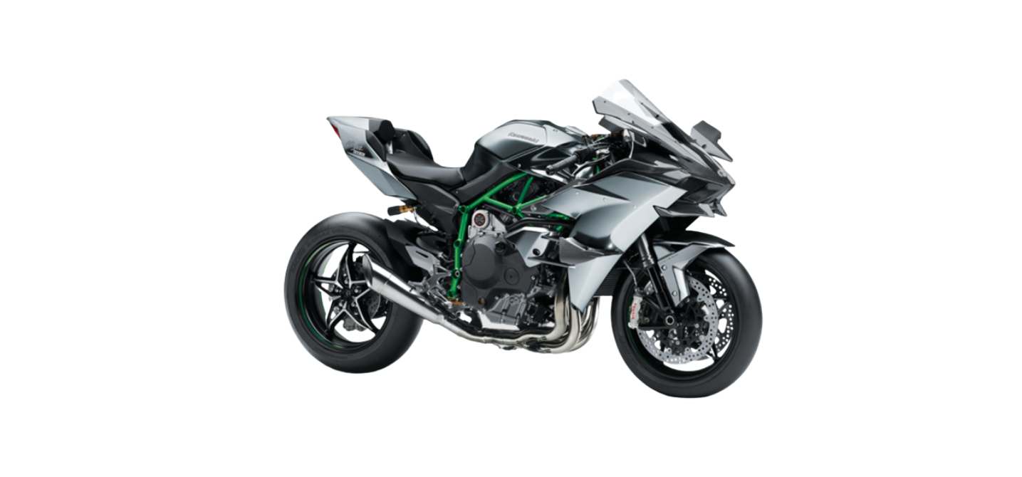
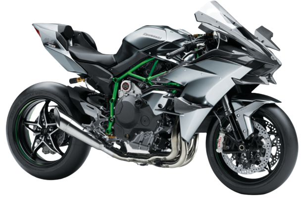
2022 Kawasaki NINJA H2 Meter Instruments Owners Manual


2022 Kawasaki NINJA H2 Meter Instruments


Meter Instruments
- Tachomerer
- Display Screen
- Ambient Brightness Sensor
The display layout can be switched from four different types. Refer to the Setting Mode section.
Display Layout (Type 1)
- Gear Position Indicator
- Bluetooth® Connection Indicator
- Economical Riding Indicator
- Speedometer
- Clock
- KTRC Indicator
- Coolant Temperature Meter
- Multifunction Display
- Odometer
- Trip Meter A/B
- Lean Angle
- Maximum Lean Angles
- Boost Temperature
- Boost Pressure (%)
- Current Mileage
- Average Mileage
- Fuel Consumption
- Average Speed
- Total Time
- Battery Voltage
- Data
- KQS Indicator
- KEBC Indicator
Display Layout (Type 2)
- Gear Position Indicator
- KEBC Indicator
- KQS Indicator
- Bluetooth® Connection Indicator
- Multifunction Display
- Odometer
- Trip Meter A/B
- Lean Angle
- Maximum Lean Angles
- Boost Temperature
- Boost Pressure (%)
- Speedometer
- Clock
- KTRC Indicator
- Throttle Gauge
- Boost Gauge
- Coolant Temperature Meter
- Acceleration/Deceleration Indicator
Display Layout (Type 3)
- Gear Position Indicator
- KEBC Indicator
- KQS Indicator
- Bluetooth® Connection Indicator
- Multifunction Display
Odometer
Trip Meter A/B
Lean Angle
Maximum Lean Angles
Boost Temperature
Boost Pressure (%) - Speedometer
- Clock
- KTRC Indicator
- Front Brake Pressure Gauge
- Boost Gauge
- Coolant Temperature Meter
- cceleration/Deceleration Indicator
Display Layout (Type 4)
- Gear Position Indicator
- KEBC Indicator
- KQS Indicator
- Bluetooth Connection Indicator
- Multifunction Display
- Odometer
- Trip Meter A/B
- Lean Angle
- Maximum Lean Angles
- Boost Temperature
- Boost Pressure (%)
- Speedometer
- Clock
- KTRC Indicator
- Coolant Temperature Meter
- Acceleration/Deceleration Indicator
Ambient Brightness Sensor
The brightness of the meter instrument is controlled automatically depending on the ambient brightness.
NOTE
Be careful not to cover the ambient brightness sensor on the meter instrument while riding the motorcycle.
Meter Instrument Brightness Setting
The brightness of the meter instrument can be adjusted manually in three levels. Refer to Brightness in the Setting Mode section.
Indicators
- Oil Pressure Warning Indicator (Red)
- Coolant Temperature Warning Indicator
- Battery Warning Indicator (Red)
- Immobilizer Warning Indicator (Red)
- Fuel Level Warning Indicator (Amber)
- Rain Mode Indicator (White)
- High Beam Indicator (Blue)
- KTRC Indicator (Yellow)
- ABS Indicator (Yellow)
- Engine Warning Indicator (Yellow)
- Shift-up Indicator (Yellow)
- Left Turn Signal Indicator (Green)
- Neutral Indicator (Green)
- Right Turn Signal Indicator (Green)
Indicator Initial Operation
When the ignition switch is turned on, all indicators go on/off as shown in the table. If any indicator does not operate as shown, have it checked by an authorized Kawasaki dealer.
- When ignition switch is turned on.
- After a few seconds
- When engine starts.
- Goes on.
- Goes off.
- goes off shorty after the motorcycle starts moVing.
When Warning Indicators Go On or Blink
When warning indicators appear, there could be a problem with a vehicle function. Follow actions in the table after stopping the vehicle in a safe place. The numbers in this column corresponds to reference numbers on page 46.
- After continuous riding on a rough road.
- When the engine is started with the stand raised and the transmission engaged, and the rear wheel turns.
- When accelerating so abruptly that the front wheel leaves the ground.
- When the ABS has been subjected to strong electrical interference.
- When tire pressure is abnormal. Adjust tire pressure.
- When a tire different in size from the standard size is being used. Replace with standard size.
- When the wheel is deformed. Replace the wheel.
When Warning Messages Display
When warning messages appear, there could be a problem with vehicle function. ave them checked by an authorized Kawasaki dealer.
ESD warning message may appear when the ignition switch is turned on with the motorcycle moving. If this message appears, first turn the ignition switch off, and then back on with the motorcycle completely stopped. The ESD warning message disappears. If it does not disappear, contact an authorized Kawasaki dealer.
Other Indicators
The immobilizer warning indicator blinking mode can be set to either on or off. Refer to the Setting Mode section.
Speedometer/Tachometer
A. Speedometer
B. Tachometer
C. Red Zone
Speedometer
The speedometer is digital and can be set for km/h or mph. The unit setting can be changed ac- cording to local regulations. Make sure the unit setting (km/h or mph) is correctly displayed before riding. Refer to the Setting Mode section.
Tachometer
The tachometer shows the engine speed in revolutions per minute (r/min, rpm).
NOTICE
Engine speed should not be allowed to enter the red zone; operation in the red zone will over-stress the engine and may cause serious engine damage.
When the ignition switch is turned on, the tachometer needle momentarily sweeps from the minimum to the maximum reading, then back the minimum reading to check its operation. If the tachometer does not operate correctly, have it checked by an authorized Kawasaki dealer.
Features
Gear Position Indicator
NOTE
lf the transmission gears are not engaged properly, the gear position indicator disappears. The gear position indicator also serves as the shift-up indicator.
Shift-up Indicator
The shift-up indicator indicates the timing for the next up shift. Before reaching the set engine speed, the gear position indicator starts blinking slowly. When the engine speed reaches the set value, the gear posi- tion indicator changes color to amber and the shift-up indicator and the gear position indicator blink rapidly.
A. Shift-up Indicator (Blink)
B. Gear Position Indicator (Change in Color)
The shift-up indicator can be selected on or off, and the set value can be adjusted.
Shift-up Indicator Setting
Refer to Vehicle Settings in the Setting Mode section.
Economical Riding Indicator (Only on display layout Type 1)
WARNING
Failing to properly observe the road ahead increases the chance of an accident resulting in severe injury or death. Do not concentrate on the economical rid- ing indicator by taking your eyes off the road; observe using pe- ripheral vision.
Acceleration/Deceleration Indicator
(Only on display layout Type 2 4)
This indicator shows the acceleration/deceleration rate of the vehicle. When acceleration is greater, the indicator moves more to the back side of the vehicle illustration. When decel- eration is greater, the indicator moves more to the front side of the vehicle illustration.
Boost Pressure Gauge
(Only on display layout Type 2/3) This gauge shows the instantaneous boost pressure in the intake air chamber.
Throttle Gauge
(Only on display layout Type 2)
The opening angle of the throttle valve in the throttle body is shown.
Front Brake Pressure Gauge
(Only on display layout Type 3)
The fluid pressure of the front brake line is shown.
KEBC Mode Indicator
The current setting of KEBC is shown. Refer to the Kawasaki Engine Brake Control (KEBC) section in the HOW TO RIDE THE MOTORCYCLE chapter.
KEBC Setting
Refer to Vehicle Settings in the Menu section.
KQS Mode Indicator
The current setting of KQS is shown. Refer to the Kawasaki Quick Shift (KQS) section in the HOW TO RIDE THE MOTORCYCLE chapter.
B. Mail Icon
Refer to Bluetooth in the Setting Mode section.
This motorcycle can connect to the smart device via built-in Bluetooth wireless technology. Using the application “RIDEOLOGY THE APP” several data of your vehicle can be accessed, and several setting items can be adjusted. Refer to the application for details
For safety, do not use a smart device while riding the motorcycle.
- Some smart devices may not be compatible even if Bluetooth technology is available.
- The Bluetooth word mark and logos are registered trademarks owned by Bluetooth SIG, Inc.
Control Buttons
The upper and lower buttons on the left handlebar and mode button on the right handlebar are used to operate the various functions of the display screen.
A. Upper Button
B. Lower Button
C. Mode Button
Multifunction Display
Push the upper or lower button to select the item. The display items are switched in the following order.
Upper Button
(Only on display layout Type 1)
Lower Button
- Flow when pushing upper button
- Flow when pushing lower button
Odometer
The odometer shows the total distance. This meter cannot be reset.
NOTE
When the figures come to 999999, the display is stopped and locked.
Trip Meter
The trip meter shows the distance traveled since it was reset.
NOTE
When the trip meter reaches 9999.9 while riding, the meter resets to 0.0 and continues counting.
How to Reset
Refer to the Multifunction Display Resetting section.
Lean Angle
This shows the lean angle of the vehicle. The more it is leaned, the larger the bar on the gauge.
Maximum Lean Angles
This shows the maximum lean angles of the vehicle by numerical value.
How to Reset
Refer to the Multifunction Display Resetting section.
Coolant Temperature
Stop the engine if the coolant temperature shows “Hi.” Pro-longed engine operation will result in severe engine damage from overheating.
The other displays shifts to the coolant temperature automatically if the coolant temperature rises above 115°C (239°F.
This shows the boost pressure of the intake air chamber by the percentage.
This shows the instantaneous rate of fuel consumption. It is renewed every 4 seconds.
When the ignition switch is turned on, the numerical value shows After a few seconds of riding the numerical value is displayed.
This shows the average rate of fuel consumption since it was reset. It is renewed every 5 seconds.
Refer to the Multifunction Display Re-setting section.
This shows the fuel consumption by numerical value counted from the start of measuring to present time. The fuel consumption display is renewed every 4 seconds.
When the battery is disconnected, the fuel consumption resets to 0.0.
Refer to the Multifunction Display Re- setting section.
This shows the average vehicle speed since it was reset.
Refer to the Multifunction Display Resetting section.
When the figures come to 99:59, the display is stopped and locked.
Refer to the Multifunction Display Resetting section.
This shows the current battery voltage.
- The battery voltage is displayed in the 9.0~ 16.0 V range. If the display range is exceeded, the indication is fixed at the maximum or minimum value.
- The battery voltage shown in this display may differ from the numerical value measured by a volt meter.
Date
This shows the date.
Multifunction Display Resetting
The following multifunction display items can be reset.
NOTE
- When pushing the upper or mode button while the item is blinking, the resetting is canceled.
- After the item has been blinking for five seconds, the resetting is canceled.
- RESET ALL” means all resettable items will be reset.
When only one resettable item is shown:
- Push the lower button and hold it. The resettable item starts blinking.
- Push the lower button to select the resettable item or “RESET ALL.”
- Push the lower button and hold it until resetting is done.
- Flow when pushing and holding the lower button
- Flow when pushing the lower button
When two resettable items are shown:
- Push the lower button and hold it.
- The resettable item starts blinking.
- The blinking item indicates that it is being selected. Push the lower button to select the item or “RESET ALL.”
- Push the lower button and hold it until resetting is done.
- Flow when pushing the lower button
When no resettable item is shown:
- Push the lower button and hold it. “RESET ALL” appears.
- Push the lower button and hold it until resetting is done.
- Flow when pushing and holding lower button
NOTE
lf the ignition switch is turned off during reseting, the reset is not carried Out.
Setting Mode
The setting mode can set some functions and display some information. To operate the setting mode:
- Push and hold the mode button until entering the setting mode.
- Push and hold the mode button until the main display returns to the ordinary display.
A. Ordinary Display
B. Setting Mode
Flow when pushing and holding mode button
NOTE
When the vehicle speed exceeds 5 km/h (3 mph), the meter ends the setting mode and returns to the ordinary display. Push the upper button or lower button to select the item. When pushing the lower button, the display items are shifted in the following order When pushing the upper button, these are shifted in the reverse order.
- Flow when pushing upper button
- Flow when pushing lower button
Unit Setting (UNIT)
The unit setting in the meter instru-ment can be changed according to local regulations. Make sure the unit setting is correctly displayed before riding.
NOTE
- Do not operate the motorcycle with the wrong speed unit (mph or km/h).
- The unit setting can be selected from four unit types.
To select the setting:
- Push and hold the mode button to enter the setting mode.
- Push the upper button or lower button to display “UNIT.”
- Push the mode button.
- Push the upper button or lower button to select the unit type
- Push the mode button.
A. Unit
- Flow when pushing mode button
- Flow when pushing upper button
- Flow when pushing lower button
Meter illumination Brightness Setting (BRIGHTNESS)
The backlight brightness can be adjusted manually in three levels.
To select the setting
- Push and hold the mode button to enter the setting mode.
- Push the upper button or lower but- ton to display “BRIGHTNESS.”
- Push the mode button.
- The main display and tachometer illuminate in the current setting.
- Push the upper button or lower button to select the mode.
- Push the mode button.
- Flow when pushing mode button
- Flow when pushing upper button
- Flow when pushing lower button
Display Mode Setting (DISPLAY MODE)
The main display can be selected from 4 different modes (Type 1 4). To select the setting:
- Push and hold the mode button to enter the setting mode.
- Push the upper button or lower but-ton to display “DISPLAY MODE.”
- Push the mode button.
- Push the upper button or lower but- ton to select the display mode.
- Push the mode button.
- Push the upper button or lower button to select the background color from black or white.
- Push the mode button.
- Flow when pushing mode button
- Flow when pushing upper button
- Flow when pushing lower button
Rain Mode Setting (RAIN MODE)
The rain mode system can be selected on or off. To select the setting:
- Push and hold the mode button to enter the seting mode.
- Push the upper button or lower button to display “RAIN MODE.”
- Push the mode button.
- Push the upper button or lower button to select “ON” or “OFF.”
- Push the mode button.
Shift-up Indicator Setting (SHIFT LAMP)
The shift-up indicator can be selected on or off. To select the setting
- Push and hold the mode button to enter the seting mode.
- Push the upper button or lower button to display “SHIFT LAMP”
- Push the mode button.
- Push the upper button or lower button to select the setting.
- Push the mode button.
- Flow when pushing mode button
- Flow when pushing upper button
- Flow when pushing lower button
Shift-up Engine Speed Setting (SHIFT REV)
The shift-up engine speed can be adjusted between 3 000 r/min (rpm) and 13 000 r/min (rpm). To adjust the setting:
- Push and hold the mode button to enter the seting mode.
- Push the upper button or lower button to display “SHIFT REV.”
- Push the mode button.
- Push the upper button or lower button to select the setting.
NOTE
- When pushing the upper button, the shift-up engine speed increases in 250 r/min (rpm) increments.
- When pushing the lower button, the shift-up engine speed decreases in 250 r/min (rpm) increments.
- lf the shift-up engine speed increases past the maximum value, it returns to the minimum value and begins increasing again.
- lf the shift-up engine speed decreases past the minimum value, it returns to the maximum value and begins decreasing again.
- Push the mode button.
- Flow when pushing mode button
- Flow when pushing upper button
- Flow when pushing lower button
WARNING
Failing to properly observe the road ahead increases the chance of an accident. Do not concern trate on the shift-up indicator by taking your eyes off the road, observe using peripheral vi- sion. When shifting down to a lower gear, do not shift at such ahigh speed that the engine rlmin (rpm) jumps excessively. only can this cause engine dam- age, but the rear wheel may skid and cause an accident. Down shifting should be done below 5 000 r/min (rpm) for each gear.
NOTICE
Engine speed should not be allowed to enter the red zone; op- eration in the red zone will over-stress the engine and may cause serious engine damage.
KEBC Setting (KEB3C)
KEBC system can be selected from two modes.
To select the setting:
- Push and hold the mode button to enter the setting mode.
- Push the upper button or lower button to display “KEBC.”
- Push the mode button.
- Push the upper button or lower button to select the setting.
- Push the mode button.
KQS Setting (KQS)
KaS system can be selected on or off. To select the setting:
- Push and hold the mode button to enter the setting mode.
- Push the upper button or lower button to display “KQS.”
- Push the mode button.
- Push the upper button or lower buton to select “ON” or “OFF.”
- Push the mode button.
- Flow when pushing mode button
- Flow when pushing upper button
- Flow when pushing lower button
KLCM Mode Setting (KLCM)
KLCM can be used in closed course. Do not use KLCM during everyday rid- ing. KLCM can be selected from three modes.
NOTE
- lf KLCM system has any problem, the setting cannot be changed.
- When the rain mode is “ON,”the setting cannot be changed.
To select the setting:
- Push and hold the mode button to shift to the setting mode.
- Push the upper button or lower but ton to display “KLCM.”
- Push the mode button.
- Push the upper button or lower button to select the mode.
- Push the mode button.
- Flow when pushing mode button
- Flow when pushing upper button
- Flow when pushing lower button
Bluetooth
NOTE
- To use the Bluetooth function, “RIDE
- LOGY THE APP” is necessary.
Bluetooth can be selected on or off. To select the setting:
- Push and hold the mode button to enter the setting mode.
- Push the upper button or lower but- ton to display “Bluetooth.”
- Push the mode button.
- Push the upper button or lower but ton to select “ON” or “OFF.”
- Push the mode button.
Turn on the Bluetooth function of the smart device and launch the app.
NOTE
lf the motorcycle detects the paired device, they connect automatically.
A. Connected Device Name
- In the pairing setting menu of the app, select “Ninja H2” and tap the connect button. The motorcycle displays the pass key (PIN) on the display screen.
- Enter the pass key (PIN) into the unpaired device.
A. Pass Key (PIN)
NOTE
- lf the motorcycle does not detect the device, bring the device closer to the meter instruments.
- To pair with other smart device, push and hold the mode button after theBluetooth is turned on. When the remaining time is appeared, operate the app.
When pushing and holding mode button
Clock Setting (CLOCK)
The clock can be selected from the 12h mode and 24h mode.
NOTE
When the battery is disconnected, the clock is reset to 1:00 (12h mode)or 13:00 (24h mode) and starts working again when the battery is connected.
To select the setting:
- Push and hold the mode button to enter the setting mode.
- Push the upper button or lower button to display “CLOCK.”
- Push the mode button.
- Push the upper button, lower button or mode button to select the setting.
- When pushing the button, the display changes as follows.
- Flow when pushing mode button
- Flow when pushing upper button
- Flow when pushing lower button
- Flow when pushing and holding the mode button
- When selecting “12h
- When selecting “24h”
Date Seting (DATE)
The date can be selected from the 3 modes. To select the setting
- Push and hold the mode button to enter the setting mode.
- Push the upper button or lower button to display “DATE.”
- Push the mode button.
- Push the upper button, lower button or mode button to select the setting. When pushing the button, the display changes as follows.
- Flow when pushing mode button
- Flow when pushing upper button
- Flow when pushing lower button
- Flow when pushing and holding the mode button
Setting Reset (RESET)
The following settings of the meter can be reset. Other settings are not reset.
Initial Setting
Multifunction Display
To reset the setting
- Push and hold the mode button to enter the setting mode
- Push the upper button or lower button to display “RESET.”
- Push the mode button.
- Push the upper button or lower button to select “NO” or “YES.”
- Flow when pushing mode button
- Flow when pushing upper button
- Flow when pushing lower button
- Push the mode button. The reset will start when selecting “YES.”
NOTE
lf the ignition switch is turned off during resetting, the reset is not carried Out.
Recent Posts
VW Jetta Engine Fuse Box Diagram
Access the comprehensive 2010-2018 VW Jetta Passenger Fuse Box Diagram to troubleshoot electrical issues effectively.…
VW Jetta Passenger Fuse Box Diagram
Explore the comprehensive VW Jetta Passenger Fuse Box Diagram to troubleshoot electrical issues effectively. Understand…
2023 Ford F-150 Lightning Fuse Box Diagram
Under Hood Fuse Box Location Remove the front luggage compartment cover. Under Hood Fuse Box…
2022 Kawasaki NINJA H2 SX SE Brake Lever Adjuster Owner’s Manual
2022 Kawasaki NINJA H2 SX SE Brake Lever Adjuster Owner's Manual NOTICE Only adjust the front…
2023 Land Rover Range Rover Evoque Exiting The Vehicle Owners Manual
2023 Land Rover Range Rover Evoque Exiting The Vehicle SINGLE LOCKING WARNING Before exiting the…
2023 Land Rover Range Rover Evoque Front Seats Owners Manual
2023 Land Rover Range Rover Evoque Front Seats FRONT SEAT SAFETY Make sure to read…
