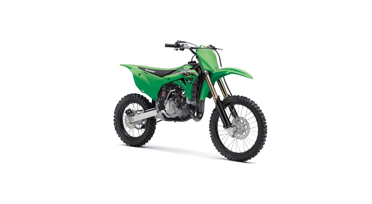
2022 Kawasaki KX85 Front Suspension
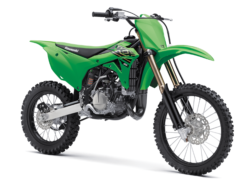
Front Suspension
Front Fork Inspection
NOTICE
Sticking muds or dusts on the sliding surface of the front fork could damage the oil seal, leading to an oil leak. Clean the sliding sur face after each ride.
- Holding the brake lever, pump the front fork back and forth manually to check for smooth operation.
- Visually inspect the front fork for oil leakage, scoring or scratches on the outer surface of the inner tube.
- If necessary, replace by an authorized Kawasaki dealer.
A. Inner Tubes
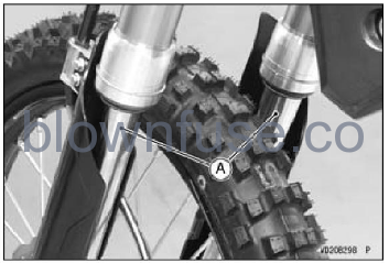
NOTICE
If the inner tube is badly bent or creased,replace it. Excessive bending, followed by subsequent straitening, can weaken the in- ner tube.
Front Fork Adjustment
Any of the following front fork adjustments should be made to tune the front suspension to the rider’s weight and the condition of the track. Basically, there are five adjustments you can make to the front fork.
Air Pressure Adjustment
Air pressure acts as a progressive spring over the entire fork travel range. Since the air pressure in the fork legs increases with normal use, the fork action on your KX will get stiffer as the race progresses.
Therefore, it is not recommended to increase the air pressure for additional springing. The KX forks aredesigned to function without added air.
Compression Damping Adjustment
This adjustment affects how quickly the fork compresses. The fork compression damping adjuster has at least 20 positions. The fully seated position (adjuster turned fully clockwise) is the hardest set ting. Turning the adjuster counterclockwise 10 clicks from the fully seated position is the standard setting, turning it counterclockwise 20 or more clicks is the softest setting.
Fork Oil Level Adjustment
The fork oil level affects only the final 100 mm (4 in.) of fork travel. A higher oil level will make the fork rebound more quickly. A lower oil level will make the fork rebound more slowly.Optional Fork Springs Optional springs, softer and stiffer than standard, are available.
Fork Height
Steering is greatly affected by the fork height (how much the outer fork tubes protrude above the up-per fork clamp). The less the fork tube protrudes, the lighter the front end becomes and the greater the tendency for understeering and washout due to weight biasing. Increasing the amount of fork tube protrusion has opposite effects. Be sure that the front tire does not touch the fender when the fork
is fully compressed. Make this adjustment in 10 mm(0.39 in.) steps.
NOTICE
The right and left fork tubes must be adjusted evenly.
Air Pressure Adjustment
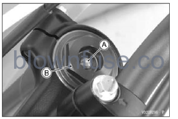
The standard air pressure in the front fork legs is atmospheric (0 kPa, 0 kgf/cm2, 0 psi). Air pressure in the fork legs increase with normal use, so the fork action stiffens during operation. Release air pres- sure from the fork legs prior to each race through the air pressure relief screw located in front fork top plug. Make sure the front forks are fully extended with the front wheel off the ground when releasing the pressure.
- Raise the front wheel off the ground using a jack (special tool: 57001-1238) and attachment (special tool: 57001-1608)
- Remove the air pressure relief screw on each front fork top plug to let the air pressure equalize. Then, tighten the screws to the specified torque.
Tightening Torque
Air Pressure Relief Screws: 1.3 Nm (0.13 kgfm, 12 in-b)
A. Air Pressure Relief Screw
B. Front Fork Top Plug
Compression Damping Adjustment
- Raise the front wheel off the ground using a jack (special tool: 57001-1238) and attachment (special tool: 57001-1608).
- Clean the bottom of the fork tubes.
- Remove the caps on the bottom of the fork tubes.
A. Cap (Both Sides)
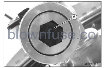
To adjust the compression damping, turn the adjuster on the compression valve assembly with a standard tip screwdriver. Adjust the compression damping to suit your preference under certain con- ditions
NOTICE
Do not force the compression damping adjuster beyond the fully seated position, or the adjusting mechanism may be damaged.
Compression Damper Settings
A. Seated Position (Adjuster Turned Fully Clockwise)
B. Softer (Counterclockwise)
C. Harder (Clockwise)
D. Standard Setting
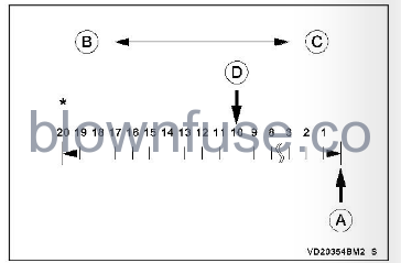
Number of turns counterclockwise usable range 20 clicks or more.
Standard Compression Damper Setting
10 clicks Counterclockwise from the fully seated position
NOTICE
The right and left fork tubes must be adjusted evenly. Install the caps on the bottom of the fork tubes.
Fork Oil Level Adjustment
Thoroughly clean the forks before disassembly.
NOTICE
Be careful not to scratch the inner tube and not to damage the dust seal. Avoid scratching or damaging the inner tube or the dust seal. Use a mild detergent and sponge out dirt with plenty of water.
NOTE
- Record the compression damper setting before disassembling.
- Set the compression damping to the softest settings before disassembly to prevent the needle of adjusters from damping. Remove the number plate (see Steering section). Remove the bolts and the front fender.
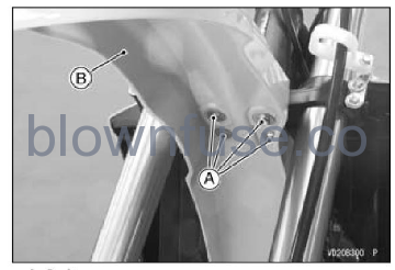
A. Bolts
B. Front Fender
- Loosen the front fork clamp bolts (upper).
- Loosen the front fork top plug.
NOTE
Do not take off the compression valve assembly.
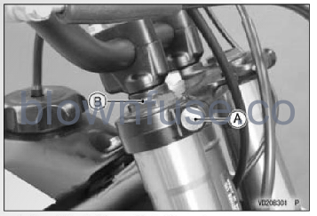
A. Front Fork Clamp Bolt (Upper)
B. Front Fork Top Plug
- Support the motorcycle using a jack (special tool: 57001-1238) and attachment (special tool: 57001-1608)
- Remove the bolts and the brake hose clamps.
- Remove the bolts and front fork protectors.
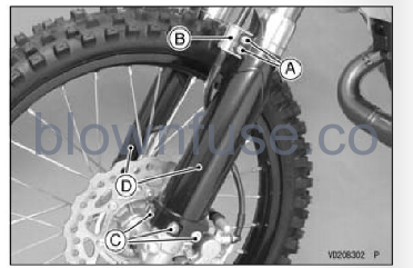
A. Bolts
B. Brake Hose Clamps
C. Bolts (Both Sides)
D. Front Fork Protectors
Loosen the front fork top plugs, and take the top plugs with the push rods off.
WARNING
The top plugs are under extreme spring pressure and may eject with great force during service. Use care when removing the top plugs. Wear eye and face protection.
- Place a suitable stand under the engine to raise the front wheel off the ground.
- Slowly compress the front fork fully by pushing up the inner tube until its stepped portion contacts the dust seal on the lower end of the outer tube.

A. Inner Tube (Stepped Portion)
B. Dust Seal
C. Outer Tube
Place a stand or other suitable support under the front wheel.
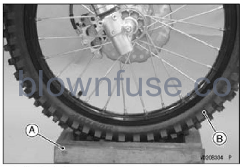
A. Suitable Support
B. Front Wheel
- While holding the front fork push rod nut with a wrench, remove the front fork top plug from the top of the push rod.
- Remove the fork spring seat and fork spring.
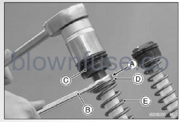
A. Front Fork Push Rod Nut
B. Wrench
C. Front Fork Top Plug
D. Fork Spring Seat
E. Fork Spring
- Remove the other fork spring in the same way as described above.
- Fill the front fork to the top of the inner tube with fork oil.
Recommended Fork Oil _
KHL15-10 (1 L): P/No. 44091-0004 Install a push rod puller (special tool: 57001-1298) onto the push rod.
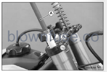
A. Push Rod Puller (Special Tool: 57001-1298)
B. Push Rod
- Fill the fork cylinder with oil by gently moving the push rod puller up and down five times.
- Fill oil between the inner tube and outer tube by pumping the outer tube up and down five times.
- Adjust the fork oil level within the adjustable range to suit your preferences.
Standard Fork Oil Level
95 +2 mm (3.74 0.08 in.)
Adjustable Range
75 115 mm (2.95 – 4.53 in.)
Remove the excess oil through the outer tube opening, using an oil level gauge (special tool: 57001-1290).
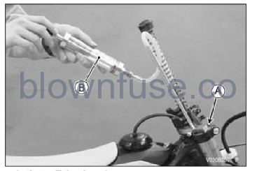
A. Outer Tube Opening
B. Oil Level Gauge (Special Tool: 57001-1290)
- Pull up the push rod puller.
- Hold the push rod with your hand and remove the push rod puller.
- Install the fork spring and the fork spring seat on the fork spring.
- Replace both top plug O-rings with new ones.
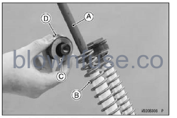
A. Push Rod Puller (Special Tool: 57001-1298)
B. Fork Spring
C. Fork Spring Seat
D. O-ring
- Check the front fork push rod nut on the bottom of the thread, and screw the front fork top plug onto the push rod.
- While holding the front fork push rod nut with a wrench, tighten it to the specified torque.
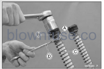
A. Front Fork Push Rod Nut
B. Front Fork Top Plug
C. Push Rod
D. Wrench
Tightening Torque
Front Fork Push Rod Nuts: 15 N m (1.5 kgfm, 11 ft:lb)
- Remove the stand and support to apply load to the vehicle.
- Tighten the front fork top plug to the specified torque.
Tightening Torque
Front Fork Top Plugs 28 N-m (2.9 kgfm, 21 ft:lb)
- Assemble the other fork tube in the same way as described above.
- Tighten the front fork clamp bolts (upper) to the specified torque.
Tightening Torque
Front Fork Clamp Bolts (Upper): 20 N m (2.0 kgfm, 15 ft:lb)
- Install the front fork protectors so that they do not touch the front fork outer tubes.
- Install the removed parts.
- Check the front brake for the proper brake effect, or no brake drag.
- Check the clutch lever and throttle for the proper operations.
Optional Fork Springs
Various fork springs are available to achieve suit- able front fork action in accordance with the rider’s weight and track condition. Harder springs stiffen the fork action and acceler- ate the rebound damping. Softer springs soften the fork action and slow down the rebound damping.
Fork Height Adjustment
Steering is greatly affected by the fork height. The less the fork height, the lighter the front end becomes and the greater the tendency for understeering and washout due to weight biasing. Increasing the fork height has opposite effects. Be sure that the front tire does not touch the fender when the fork is fully compressed. Make this adjustment in 10 mm steps.
NOTICE
Both fork heights should be adjusted evenly.
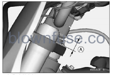
A. Fork Height
Standard Fork Height
18 mm (0.71 in.)
Between the top end of the outer tube and upper surface of the steering stem head.
