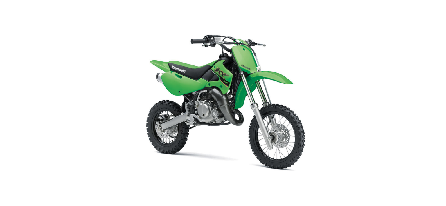
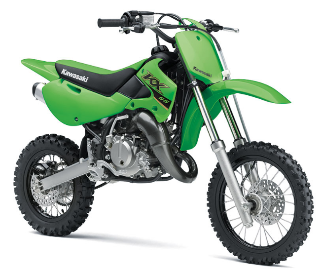
2022 Kawasaki KX65 Piston Owners Manual


2022 Kawasaki KX65 Piston


Piston
Piston Removal
- Turn the fuel tap lever to the OFF position.
- Drain the coolant (See the Cooling System sec- tion).
- Remove the seat and the left and right side covers.
- Remove the left and right radiator covers, and disconnect the clutch cable (see the Clutch section)
- Disconnect the fuel hose from the fuel tap.
- Remove the fuel tank mounting bolt and band.
- Remove the fuel tank.
A. Fuel Tank Mounting Bolt
B. Fuel Tank Mounting Band
C. Fuel Tank
- Remove the muffler (See the Exhaust System section).
- Remove the springs holding the exhaust pipe.
A. Springs
Remove the exhaust pipe damper mounting bolts, and pull the exhaust pipe off toward the front.
A. Exhaust Pipe Damper Mounting Bolts
- Remove the exhaust pipe gasket.
- Loosen the clamp screws and pull the carburetor out of the cylinder intake joint and air cleaner joint.
A. Clamp Screws
- Disconnect the coolant hose at the cylinder head.
- Remove the spark plug.
- Remove the cylinder head nuts, and take off the cylinder head and gasket.
A. Cylinder Head Nuts
B. Cylinder Head
C. Cylinder Head Gasket
- Remove the cylinder nuts.
- Lift off the cylinder, and remove the cylinder base gasket. If necessary, tap lighthly around the base of the cylinder with a plastic mallet, taking care not to damage the cylinder.
A. Cylinder Nuts
B. Cylinder
- Stuff a clean cloth into the crankcase opening around the connecting rod so that no parts will fall into the crankcase.
- Remove one of the piston pin snap rings with nee- dle nose pliers.
- Push the piston pin out from the side that the snap ring was removed and remove the piston. Use a piston pin puller assembly (special tool), if the pin is tight.
A. Piston Pin Puller Assembly: 57001-910
Piston Ring Removal
Carefully spread the ring gap with your thumbs and then push up on the opposite side of the ring to remove it.
A. Piston Ring
Piston Ring, Piston Ring Groove Inspection
- Visually inspect the piston rings and the piston ring grooves.
- If the rings are worn unevenly or damaged, they must be replaced.
- If the piston ring grooves are worn unevenly or damaged, the piston must be replaced and fitted with new rings.
- Check for uneven the piston ring groove wear by inspecting the ring seating.
- The piston rings should fit perfectly parallel to the groove surfaces. If not, the piston must be re- placed.
- With the piston ring in its groove, make several measurements with a thickness gauge to deter mine piston ring/groove clearance.
A. Thickness Gauge
Piston Ring/Groove Clearance (Top and Second)
- If the piston ring/groove clearance exceeds the service limit, measure the thickness of the piston ring.
- If the piston ring has worn down to less than the service limit, replace the ring; if the piston ring groove width exceeds the service limit, replace the piston.
Piston Ring Thickness (Top and Second)
Piston Ring Groove Width (Top and Second)
Piston, Piston Pin, Connecting Rod Wear
Inspection
- If the piston pin hole groove shows excessive wear, replace the piston.
- Measure the diameter of the piston pin with a micrometer.
- If the piston pin diameter is less than the service limit at any point, replace the piston pin.
Piston Pin Diameter
- Using a cylinder gauge, measure the diameter of the both of piston pin holes in the piston and the inside diameter of the connecting rod small end.
- If either piston pin hole diameter exceeds the ser- vice limit, replace the piston.
Piston Pin Hole Diameter
Connecting Rod Small End Inside Diameter
Check the needle bearing.
NOTE
- The rollers in a needle bearing normally wear very little, and wear is difficult to measure. Instead of measuring, inspect the bearing for abrasion, color change or other damage.
- If there is any doubt as to the condition of a needle bearing, replace the bearing and piston pin.
A. Snap Ring
B. Piston Pin
C. Piston Pin Hole
D. Needle Bearing
Piston Installation
- Install all parts in the reverse order of removal.
- Stuff a clean cloth into the crankcase opening around the connecting rod so that no parts will fall into the crankcase.
- Scrape any carbon off of the piston, then lightly polish the piston with fine emery cloth.
- Clean carbon and dirt out of the piston ring grooves using a suitable tool.
NOTICE
Carbon particles can be very abrasive to pis- ton rings. Don’t allow such particles to fall onto the cylinder walls.
- When installing the piston ring on the piston, note the following:
- First fit one end of the piston ring against the pin in the ring groove, spread the ring opening with the other hand and then slip the ring into the groove.
- The top ring has a “1N” mark on its upper surface.
- The second ring has a “2N” mark on its upper sur- face.
- Install each ring so that the marked side faces up- ward.
A. “1N” Mark
B. 2N” Mark
NOTE
Install the piston ring so that the pin in the piston ring groove is between the ends of the piston ring.
A. Pin
- Apply 2-stroke engine oil to the connecting rod needle bearing and the piston pin.
- Install the piston so that the “IN” mark faces toward the back (intake side) of the engine.
A. Piston
B. “IN” Mark
When installing a piston pin snap ring, compress it only enough to install it and no more.
NOTICE
Do not reuse snap rings, as removal weakens and deforms them. They could fall out and score the cylinder wall.
Fit a new piston pin snap ring into the side of the piston so that the snap ring ends do not coincide with the notch in the edge of the piston pin hole.
A. Snap Ring
B. Snap Ring Ends
C. Notch
Cylinder, Cylinder Head installation
- Scrape any carbon out of the exhaust port.
- Check for mineral deposits and rust in the cylinder water jacket, and remove them if necessary.
- Replace the cylinder base gasket with a new one.
- Apply engine oil to the piston surface, piston rings and cylinder bore.
- Check that the pin in each piston ring groove is between cylinder over each ring, pressing in op- posite sides of the piston rings as necessary. Be certain that the piston rings do not slip out of position.
A. Pin
Tighten the cylinder nuts to the specified torque in a crisscross patterm.
Cylinder Nut Tightening Torque
25 Nm (2.5 kgfm, 18 ftlb)
- Scrape out any carbon and clean the cylinder head with a high flash-point solvent.
- Check for mineral deposits and rust in the cylinder head water jacket, and remove them if necessary.
- Replace the cylinder head gasket with a
- Install a new cylinder head gasket with the side marked “UP” facing up toward exhaust side.
A. Cylinder Head Gasket
B. “UP” Mark
C. Exhaust Side
D. Cylinder Head
Tighten the cylinder head nuts to the specified torque in a crisscross pattern.
Cylinder Head Nut Tightening Torque
25 Nm (2.5 kgfm, 18 ft:lb)
- Install the spark plug.
- Connect the coolant hose to the cylinder head.
- When installing the carburetor, note the following:
- Being careful not to bend or otherwise damage the jet needle, align the groove in the throttle valve with the guide pin in the carburetor body.
A. Groove
B. Guide Pin
- Check that the throttle valve goes all the way down into the carburetor body and slides smoothly.
- Fit the ridge on the carburetor body into the notch on the carburetor holder.
A. Ridge
B. Notch
- Tighten the clamp screw on the air cleaner joint and cylinder intake joint securely.
- Install the exhaust pipe, gasket, and muffler.
- Install the fuel tank, and tighten the fuel tank mounting bolt.
- Route the air vent hose and overflow hose through the clamp on the crankcase.
NOTICE
Always keep the hoses free from obstruction, and make sure they do not get pinched by the chain or shock absorber.
- Turn the fuel tap lever to the ON position, and check for fuel leakage from the carburetor.
- Install the parts removed.
- Fill the radiator up to the bottom of the radiator filler neck with coolant (See the “Cooling System” chapter)
- Check the coolant level.
Recent Posts
VW Jetta Engine Fuse Box Diagram
Access the comprehensive 2010-2018 VW Jetta Passenger Fuse Box Diagram to troubleshoot electrical issues effectively.…
VW Jetta Passenger Fuse Box Diagram
Explore the comprehensive VW Jetta Passenger Fuse Box Diagram to troubleshoot electrical issues effectively. Understand…
2023 Ford F-150 Lightning Fuse Box Diagram
Under Hood Fuse Box Location Remove the front luggage compartment cover. Under Hood Fuse Box…
2022 Kawasaki NINJA H2 SX SE Brake Lever Adjuster Owner’s Manual
2022 Kawasaki NINJA H2 SX SE Brake Lever Adjuster Owner's Manual NOTICE Only adjust the front…
2023 Land Rover Range Rover Evoque Exiting The Vehicle Owners Manual
2023 Land Rover Range Rover Evoque Exiting The Vehicle SINGLE LOCKING WARNING Before exiting the…
2023 Land Rover Range Rover Evoque Front Seats Owners Manual
2023 Land Rover Range Rover Evoque Front Seats FRONT SEAT SAFETY Make sure to read…
