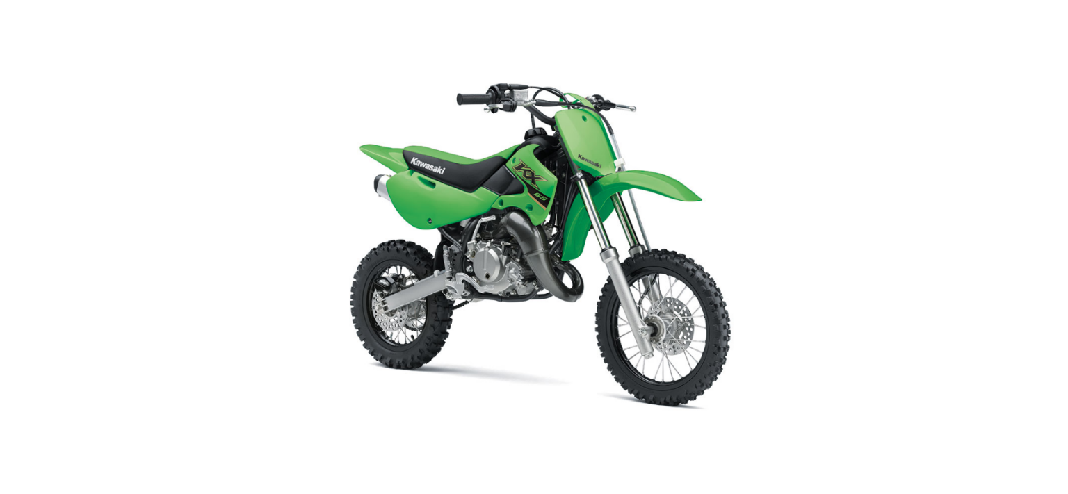
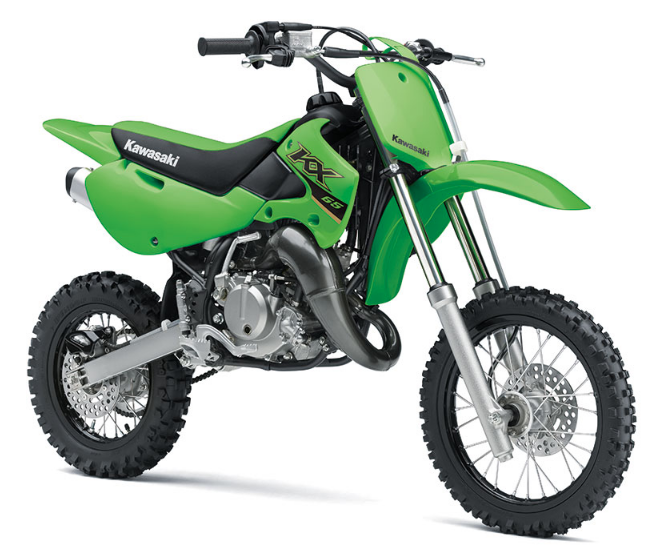
2022 Kawasaki KX65 Clutch Owners Manual


2022 Kawasaki KX65 Clutch


Clutch
Clutch Lever Adjustment
Proper clutch lever play is 8 13 mm (0.30.5 in.). Lever play increases with cable stretch and friction plate wear, requiring periodic adjustment. When the clutch lever play is out of specification, first try adjusting it at the clutch lever as follows.
- Slide the clutch lever dust cover back.
- Loosen the locknut, turn the adjuster to obtain the proper amount of clutch lever play, then tighten the locknut.
A. Clutch Lever
B. Locknut
C. Adjuster
D.813 mm (0.3 0.5 in.)
E. Dust Cover
- Slide back the clutch lever dust cover.
- Loosen the locknut at the clutch lever.
- Turn the adjuster in all the way, then tighten the locknut.
- Loosen the nuts and turn them so that the clutch lever play is 8 13 mm (0.3 0.5 in.).
If the clutch lever play cannot be adjusted at the clutch lever, make the adjustment further down the cable as follows.
A. Nuts
- Tighten the nuts.
- Start the engine, check that the clutch does not slip and it releases properly.
- Slide the dust cover back into place.
Friction Plate Removal
- Drain the transmission oil and coolant (see the Transmission Oil section and Cooling System section).
- Give plenty of play to the clutch cable by turning the adjuster.
- Line up the slots in the clutch lever, locknut, and adjuster, and then free the cable from the clutch lever.
A. Locknut
B. Adjuster
C. Slots
Free the clutch inner cable tip from the clutch release lever.
NOTICE
Do not remove the clutch release shaft unless it is absolutely necessary. If the clutch release shaft is removed, the oil seal must be replaced with a new one. Remove the kick pedal.
A. Kick Pedal
B. Clutch Release Lever
Remove the cotter pin, pivot pin and washer from the rear brake pedal.
A. Rear Brake Pedal Pivot Pin
B. Cotter Pin
Remove the brake pedal mounting bolt and take off the brake pedal and return spring.
A. Brake Pedal Mounting Bolt
B. Brake Pedal Return Spring
- Loosen the water pump hose clamp, and disconnect the lower end of the water pump hose.
- Unscrew the water pump cover bolts, and remove the water pump cover and gasket.
A. Water Pump Hose Clamp
B. Water Pump Cover
C. Water Pump Cover Bolt
Remove the impeller bolt, and take out the impeller and washer.
A. Impeller Bolt
B. Impeller
- Remove the right engine cover mounting bolt after pulling off the lower end of the coolant hose.
- Turn the clutch release lever toward the rear, and remove the right engine cover and gasket.
A. Coolant Hose
B. Right Engine Cover
C. Bolt
Remove the clutch pusher, adjusting washer (If provided) and clutch spring plate pusher.
A. Clutch Pusher
B. Clutch Spring Plate Pusher
The adjusting washer may be installed between the clutch pusher and the bearing.
A. Clutch Pusher
B. Adjusting Washer
C. Bearing
D. Clutch Spring Plate Pusher
- Remove the magneto cover.
- Hold the magneto flywheel steady with the fly- wheel holder to prevent clutch from rotating.
A. Flywheel Holder
Remove the clutch hub bolt, clutch spring bolts. clutch spring holder, springs and clutch hub.
A. Clutch Hub Bolt
B. Clutch Spring Bolts (6)
C. Clutch Spring Holder
D. Clutch Hub
Remove the friction plates and steel plates.
Friction Inspection
- Visually inspect the friction and steel plates to see if they show any signs of seizure, or uneven wear.
- If any plates show signs of damage, replace all friction plates and steel plates as a set.
- Measure the thickness of the friction and steel plates at several points with vernier calipers.
- If they have worn past the service limit, replace them with new ones. and Steel
A. Thickness
B. Friction Plate
Friction and Steel Plate Warp Inspection
Place each friction plate and steel plate on a surface plate, and measure the amount of friction plate and steel plate warp with a thickness gaugeIf any plate is warped over the service limit, replace it with a new one.
Friction and Steel Plate Warp
A. Surface Plate
B. Friction or Steel Plate
C. Thickness Gauge
Friction and Steel Plate Installation
- Install all parts in the reverse order of removal.
- Install the friction plates and steel plates, alternating between the two; be sure to start and finish with a friction plate.
A. Friction and Steel Plates
NOTICE
If dry steel plates and friction plates are installed, apply transmission oil to the surfaces of each plate to avoid clutch plate seizure.
- Install the clutch hub, springs and clutch spring holder.
- Tighten the clutch hub bolt and clutch spring bolts.
- Apply molybdenum disulfide grease to the clutch spring plate pusher.
- Install the clutch pusher, adjusting washer (If pro vided) and clutch spring plate pusher.
- Install the magneto cover and gasket.
- Apply molybdenum disulfide grease to the water pump shaft to prevent water pump seal damage.
NOTICE
If the right engine cover is installed without greasing the water pump shaft, the pump seal could be damaged.
A. Apply grease.
- Turn the clutch release lever toward the rear.
- Place a new right engine cover gasket in position with a thin layer of grease.
- Apply a high-temperature grease to the kick shaf oil seal lips and kick shaft spline.
- Install the right engine cover to the crankcase making sure that the two dowel pins are installed between the making surfaces.
- Route the breather hose through the clamp and position it as shown with the right engine cover mounting bolt.
A. Dowel Pins
B. Breather Hose
C. Clamp
Tighten the right engine cover mounting bolts.
Right Engine Cover Mounting Bolt Tightening Torque
9.4 Nm (0.96 kgfm, 83 in-lb) Check the clutch release lever position by measuring the position distance between the lever and the cable bracket while pushing the clutch release lever lightly forward.
A. Clutch Release Lever
B. Push forward
C. Cable Bracket
D. Position Distance (Between Lever and Cable Bracket)
Position Distance
Standard 36 44 mm (1.41.7 in.)
- If the lever position is not within the standard, select the correct number of adjusting washer ac cording to the following table
- When adjustment is necessary, remove the clutch pusher.
A. Clutch Pusher
B. Adjusting Washer
Adjusting Washer
Part No. 92200-1197 Thickness 0.8 mm (0.03 in.)
Clutch Release Lever Position and Adjusting Washer Selection
- Connect the lower end of the coolant hose, and tighten the clamp screw securely.
- Install the impeller and washer to the right engine cover, and tighten the impeller bolt.
Impeller Bolt Tightening Torque
L8.3 Nm (0.85 kgfm, 74 in-b) Place a new water pump cover gasket, and install the water pump cover, and tighten the water pump cover bolt.
Water Pump Cover Bolt Tightening Torque
9.4 Nm (0.96 kgfm, 83 in lb)
- Connect the lower end of the water pump hose, and tighten the clamp screw securely.
- Check the brake pedal O-ring for damage, and if necessary, replace them with a new one.
- Apply a high-temperature grease to the shaft portion of the rear brake pedal, install the rear brake pedal and attach the return spring onto the frame.
Brake Pedal Mounting Bolt Tightening Torque
25 Nm (2.5 kgfm, 18 ft-lb)
- Install a new cotter pin, pivot pin and washer to the rear brake pedal, and spread the ends of the cotter pin.
- Install the kick pedal, and connect the clutch cable.
Kick Pedal Bolt Tightening Torque
9.4 Nm (0.96 kgfm, 83 in-lb) Test the braking power and check that there is no brake drag.
WARNING
Air in the brake lines diminishes braking performance and can cause an accident resulting in injury or death. If the brake lever or pedal feels mushy when it is applied, there might be air in the brake lines or the brake may be defective. Have the brake checked immediately by an authorized Kawasaki dealer.
- Adjust the clutch cable.
- Check the transmission oil level and coolant level.
- Install the parts removed.
Recent Posts
VW Jetta Engine Fuse Box Diagram
Access the comprehensive 2010-2018 VW Jetta Passenger Fuse Box Diagram to troubleshoot electrical issues effectively.…
VW Jetta Passenger Fuse Box Diagram
Explore the comprehensive VW Jetta Passenger Fuse Box Diagram to troubleshoot electrical issues effectively. Understand…
2023 Ford F-150 Lightning Fuse Box Diagram
Under Hood Fuse Box Location Remove the front luggage compartment cover. Under Hood Fuse Box…
2022 Kawasaki NINJA H2 SX SE Brake Lever Adjuster Owner’s Manual
2022 Kawasaki NINJA H2 SX SE Brake Lever Adjuster Owner's Manual NOTICE Only adjust the front…
2023 Land Rover Range Rover Evoque Exiting The Vehicle Owners Manual
2023 Land Rover Range Rover Evoque Exiting The Vehicle SINGLE LOCKING WARNING Before exiting the…
2023 Land Rover Range Rover Evoque Front Seats Owners Manual
2023 Land Rover Range Rover Evoque Front Seats FRONT SEAT SAFETY Make sure to read…
