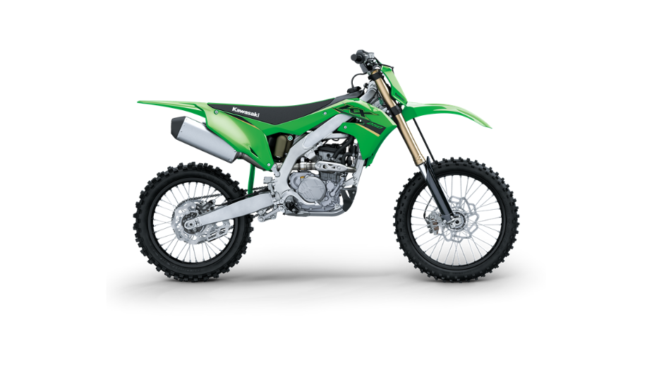
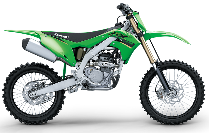
2022 Kawasaki KX250 Steering Owners Manual


2022 Kawasaki KX250 Steering


Steering
The steering should always be kept adjusted so
that the handlebars will turn freely but not have ex-
cessive play.
Steering Inspection
- To check the steering adjustment, raise the front wheel off the ground using a jack (special tool: 57001-1238) and attachment (special tool: 57001 -1608).
- Push the handlebars lightly to both side. If the handlebars continues moving under its own momentum, the steering is normal.
- Squatting in front of the motorcycle, grasp the lower ends of the front fork at the axle, and push and pull the front fork back and forth. If play is felt, the steering is too loose and needs to be adjusted.
A. Push and Pull
Steering Adjustment
- Raise the front wheel off the ground using a jack (special tool: 57001-1238) and attachment (special tool: 57001-1608).
- Unlock the clamp of the number plate.
- Remove the bolt.
- Clear the projections and remove the number plate.
A. Clamp
B. Bolt
C. Projections
D. Number Plate
- Remove the handlebars (see Adjustable Ergonomics section).
- Loosen the left and right front fork clamp bolts (up- per).
- Remove the steering stem head nut, and remove the steering stem head.
A. Steering Stem Head
B. Steering Stem Head Nut
C. Front Fork Clamp Bolts (Upper)
Turn the steering stem nut with a stem nut wrench (special tool: 57001-1100 or 57001-1863) to ob- tain the proper adjustment.
A. Steering Stem Nut
B. Stem Nut Wrench (Special Tool: 57001-1100 or 57001-1863)
- Install the steering stem head to the original position.
- Apply the specified torques to the steering stem head nut and front fork clamp bolts (upper).
Tightening Torque
Steering Stem Head Nut: 100 Nm (10.2 kgf m, 73.8 ft:lb) Front Fork Clamp Bolts (Upper): 23 Nm (2.3 kgfm, 17 ftlb)
NOTE
- Tighten the two clamp bolts altermately two times to ensure even tightening torque.
- Install the handlebars (see Handlebar Position Ad- justment), and check the steering again and read- just it if necessary
- Check the front brake for the proper brake effect, or no brake drag.
- Check the clutch lever and throttle for the proper operations.
- Install the number plate, and tighten the bolt.
Recent Posts
VW Jetta Engine Fuse Box Diagram
Access the comprehensive 2010-2018 VW Jetta Passenger Fuse Box Diagram to troubleshoot electrical issues effectively.…
VW Jetta Passenger Fuse Box Diagram
Explore the comprehensive VW Jetta Passenger Fuse Box Diagram to troubleshoot electrical issues effectively. Understand…
2023 Ford F-150 Lightning Fuse Box Diagram
Under Hood Fuse Box Location Remove the front luggage compartment cover. Under Hood Fuse Box…
2022 Kawasaki NINJA H2 SX SE Brake Lever Adjuster Owner’s Manual
2022 Kawasaki NINJA H2 SX SE Brake Lever Adjuster Owner's Manual NOTICE Only adjust the front…
2023 Land Rover Range Rover Evoque Exiting The Vehicle Owners Manual
2023 Land Rover Range Rover Evoque Exiting The Vehicle SINGLE LOCKING WARNING Before exiting the…
2023 Land Rover Range Rover Evoque Front Seats Owners Manual
2023 Land Rover Range Rover Evoque Front Seats FRONT SEAT SAFETY Make sure to read…
