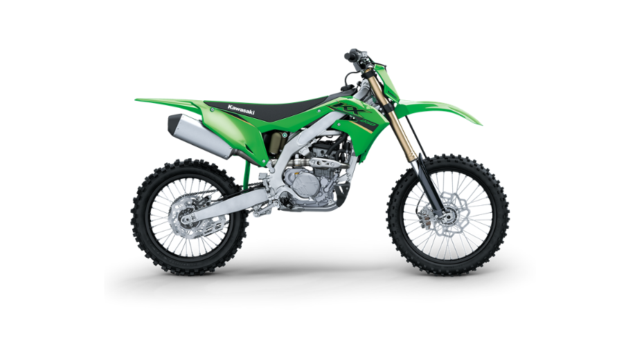
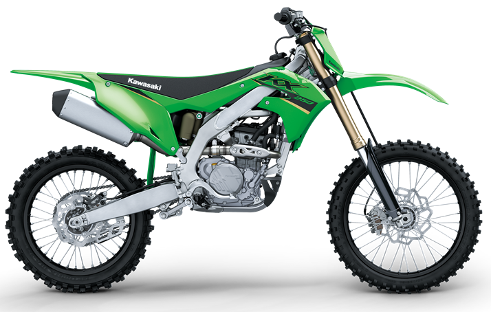
2022 Kawasaki KX250 Adjustable Ergonomic Owners Manual


2022 Kawasaki KX250 Adjustable Ergonomic


Adjustable Ergonomics
To suit various riding positions, the handlebar holder position can be changed and the handlebars can be adjusted by turning the handlebar holders around (180°). The footpeg position can also be changed to suit the rider’s preference.
Handlebar Position Adjustment
- Remove the number plate (see Steering section).
- Remove the cover and the handlebar pad.
- Check the handlebars for damage or cracks.
- Remove the handlebar clamp bolts, the clamps and the handlebars.
A. Handlebar Holder
B. Handlebar Clamp Bolts
C. Handlebar Clamps
D. Handlebars
Remove the handlebar holder nuts, washers, handlebar holders and dampers
A. Handlebar Holder Nuts
B. Washers
C. Handlebar Holder
D. Dampers
Select the handlebar position.
A. Dampers
B. Flat Surfaces
Install the rounded washers and the handlebar holders.
NOTE
- lnstall the rounded washer so that the round part fits on the damper.
- Replace the handlebar holder nuts with new ones.
- Apply engine oil to the handlebar clamp bolts.
- Put the handlebars onto the handlebar holders.
- Temporarily install the handlebar clamps.
- Hand tighten the handlebar clamp bolts.
- Tighten the handlebar holder nuts to the specified torque
Tightening Torque
Handlebar Holder Nuts: 35 Nm (3.6 kgf-m, 26 ft:lb)
- Position the handlebars and use the gauge marks to check its alignment in the clamps. should be equal marks showing on each side of the clamps.
- Tighten the front and rear handlebar clamp bolts equally. If the handlebar clamps are correctly in- stalled, there will be even gaps on the front and rear sides of the clamp after the bolts are torqued.
Tightening Torque
Handlebar Clamp Bolts: 25 Nm (2.5 kgfm, 18 ft:b)
NOTE
Tighten the two clamp bolts alternately two times to ensure even tightening torque.
A. Handlebar Clamps
B. Clamp Bolts
C. Gap
Install the cover and the handlebar pad so that the fasteners part of the cover faces backward.
A. Cover
B. Handlebar Pad
C. Fasteners Part
D. Backward
- Check the front brake for the proper brake effect, or no brake drag.
- Check the clutch lever and throttle for the proper operations.
- Install the number plate (see Steering section).
Recent Posts
VW Jetta Engine Fuse Box Diagram
Access the comprehensive 2010-2018 VW Jetta Passenger Fuse Box Diagram to troubleshoot electrical issues effectively.…
VW Jetta Passenger Fuse Box Diagram
Explore the comprehensive VW Jetta Passenger Fuse Box Diagram to troubleshoot electrical issues effectively. Understand…
2023 Ford F-150 Lightning Fuse Box Diagram
Under Hood Fuse Box Location Remove the front luggage compartment cover. Under Hood Fuse Box…
2022 Kawasaki NINJA H2 SX SE Brake Lever Adjuster Owner’s Manual
2022 Kawasaki NINJA H2 SX SE Brake Lever Adjuster Owner's Manual NOTICE Only adjust the front…
2023 Land Rover Range Rover Evoque Exiting The Vehicle Owners Manual
2023 Land Rover Range Rover Evoque Exiting The Vehicle SINGLE LOCKING WARNING Before exiting the…
2023 Land Rover Range Rover Evoque Front Seats Owners Manual
2023 Land Rover Range Rover Evoque Front Seats FRONT SEAT SAFETY Make sure to read…
