Edge
2021 Ford Edge Fuse Box Diagram


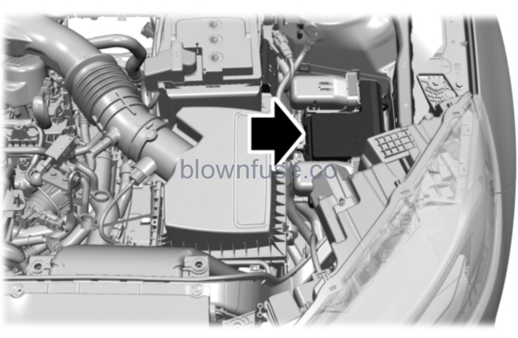
Under Hood Fuse Box Location


Under Hood Fuse Box Diagram – Top
| Fuse or Relay Number | Fuse Rating | Protected Component |
|---|---|---|
| 1 | — | Not used. |
| 2 | — | Starter relay. |
| 3 | 15 A | Rear wiper. Rain sensor. Rear washer pump relay coil. |
| 4 | — | Blower motor relay. |
| 5 | 20 A | Power point 3 – back of console. |
| 6 | — | Not used. |
| 7 | 20 A | Powertrain control module – vehicle power 1. |
| 8 | 20 A | Powertrain control module – vehicle power 2. Canister vent. Vapor blocking valve. Heated oxygen post. |
| 9 | — | Powertrain control module relay. |
| 10 | 20 A | Power point 1 – driver front. |
| 11 | 15 A | Powertrain control module – vehicle power 4. |
| 12 | 15 A | Powertrain control module – vehicle power 3. All-wheel drive module relay coil. Active grille shutters. Active transmission warm up. Auxiliary cooling pump. Electric compressor bypass. Vacuum on demand valve. A/C compressor. |
| 13 | — | Not used. |
| 14 | — | Not used. |
| 15 | — | Run-start relay. |
| 16 | 20 A | Power point 2 – console bin. |
| 17 | 20 A | Power point 4 – luggage compartment. |
| 18 | — | Not used. |
| 19 | 10 A | Run-start electronic power assist steering. |
| 20 | 10 A | Headlamp leveling. |
| 21 | — | Not used. |
| 22 | 10 A | Air conditioner clutch solenoid. |
| 23 | 15 A | Blind spot information system. Rear view camera. Forward looking radar. Voltage quality module (start/stop). Front split view camera. Front split view camera module. |
| 24 | — | Not used. |
| 25 | 10 A | Run-start anti-lock brake system. |
| 26 | 10 A | Run-start powertrain control module. |
| 27 | — | Not used. |
| 28 | 10 A | Rear window washer pump. |
| 29 | — | Not used. |
| 30 | — | Not used. |
| 31 | — | Not used. |
| 32 | — | Electronic fan 1 relay. |
| 33 | — | A/C clutch relay. |
| 34 | — | Not used. |
| 35 | — | Not used. |
| 36 | — | Not used. |
| 37 | — | Not used. |
| 38 | — | Electronic fan 2 relay. |
| 39 | — | Electronic fan 3 relay. |
| 40 | — | Horn relay. |
| 41 | — | Steering column lock relay. |
| 42 | — | Fuel pump relay. |
| 43 | 10 A | 2nd row easy fold seat release. |
| 44 | — | Not used. |
| 45 | — | Not used. |
| 46 | — | Not used. |
| 47 | — | Not used. |
| 48 | 15 A | Steering column lock relay power. |
| 49 | — | Not used. |
| 50 | 20 A | Horn. |
| 51 | — | Not used. |
| 52 | — | Not used. |
| 53 | — | Not used. |
| 54 | 10 A | Brake on-off switch. |
| 55 | 10 A | Alternator sensor. |
| 86 | – | Not used. |
Under Hood Fuse Box – Bottom
Accessing the Fuse Box
- Release the latches on both sides of the fuse box.
- Raise the inboard side of the fuse box from the cradle.
- Move the fuse box toward the center of the engine compartment.
- Pivot the outboard side of the fuse box to access the bottom side.
| Fuse or Relay Number | Fuse Rating | Protected Component |
|---|---|---|
| 56 | — | Not used. |
| 57 | — | Not used. |
| 58 | 30 A | Fuel pump feed. |
| 59 | 40 A | Electronic fan 3. |
| 60 | 40 A | Electronic fan 1. |
| 61 | — | Not used. |
| 62 | 50 A | Body control module 1. |
| 63 | 25 A | Electronic fan 2. |
| 64 | — | Not used. |
| 65 | 20 A | Front heated seat. |
| 66 | 15 A | Not used (spare). |
| 67 | 50 A | Body control module 2. |
| 68 | 40 A | Heated rear window. |
| 69 | 30 A | Anti-lock brake system valves. |
| 70 | 30 A | Passenger seat. |
| 71 | — | Not used. |
| 72 | — | Not used. |
| 73 | 20 A | Rear heated seats. |
| 74 | 30 A | Driver seat module. Driver seat power. |
| 75 | 25 A | Wiper motor 1. |
| 76 | 30 A | Power liftgate module. |
| 77 | 30 A | Climate control seat module. |
| 78 | 40 A | Trailer lighting module. |
| 79 | 40 A | Blower motor. |
| 80 | 25 A | Wiper motor 2. |
| 81 | 40 A | 110 V inverter. |
| 82 | – | Not used. |
| 83 | — | Not used. |
| 84 | 30 A | Starter motor solenoid. |
| 85 | — | Not used. |
| 87 | 60 A | Anti-lock brake system pump. |
Body Control Module Fuse Box Location
Body Control Module Fuse Box Diagram
| Fuse or Relay Number | Fuse Rating | Protected Component |
|---|---|---|
| 1 | – | Not used. |
| 2 | 10 A | Delayed accessory – power inverter logic, moonroof logic and driver window switch power. |
| 3 | 7.5 A | Memory seats. Lumbar. Wireless accessory charging. |
| 4 | 20 A | Subwoofer amplifier. |
| 5 | – | Not used. |
| 6 | 10 A | Not used (spare). |
| 7 | 10 A | Gearshift module. |
| 8 | 5 A | Power liftgate module. Hands free liftgate module. Embedded modem. |
| 9 | 5 A | Keypad. |
| 10 | – | Not used. |
| 11 | – | Not used. |
| 12 | 7.5 A | Climate control module. Enhanced central gateway module. |
| 13 | 7.5 A | Instrument cluster. Steering column control module. |
| 14 | 15 A | Not used (spare). |
| 15 | 15 A | SYNC module. |
| 16 | – | Not used. |
| 17 | 7.5 A | Headlamp control module. |
| 18 | 7.5 A | Not used (spare). |
| 19 | 5 A | Not used (spare). |
| 20 | 5 A | Push button ignition switch. |
| 21 | 5 A | In-vehicle temperature and humidity sensor. |
| 22 | 5 A | Not used (spare). |
| 23 | 30 A | Driver door window and mirror. Driver door module. Driver door lock indicator. Driver lock switch illumination. |
| 24 | 30 A | Moonroof. |
| 25 | 20 A | Amplifier. |
| 26 | 30 A | Front passenger door window and mirror. Front passenger door module. Front passenger lock indicator. Front passenger switch illumination. |
| 27 | 30 A | Not used (spare). |
| 28 | 30 A | Not used (spare). |
| 29 | 15 A | Enhanced central gateway power – OBD connector. |
| 30 | 5 A | Not used (spare). |
| 31 | 10 A | Radio transceiver module. Multi-function display. Integrated control panel. |
| 32 | 20 A | Radio. |
| 33 | – | Not used. |
| 34 | 30 A | Run-start bus (fuse 17, 18, 21, 22, 35, 36, 37, circuit breaker 38). |
| 35 | 5 A | Passenger airbag deactivation indicator. |
| 36 | 15 A | Rear heated seat module. |
| 37 | 20 A | Heated steering wheel. Auto-dimming interior mirror. Automatic high beam and lane departure mirror module. |
| 38 | 30 A | Circuit breaker. Right-hand rear window power. Left-hand rear window power. |
2021 Ford Edge Owners Manual
Recent Posts
VW Jetta Engine Fuse Box Diagram
Access the comprehensive 2010-2018 VW Jetta Passenger Fuse Box Diagram to troubleshoot electrical issues effectively.…
1 year ago
VW Jetta Passenger Fuse Box Diagram
Explore the comprehensive VW Jetta Passenger Fuse Box Diagram to troubleshoot electrical issues effectively. Understand…
1 year ago
2023 Ford F-150 Lightning Fuse Box Diagram
Under Hood Fuse Box Location Remove the front luggage compartment cover. Under Hood Fuse Box…
2 years ago
2022 Kawasaki NINJA H2 SX SE Brake Lever Adjuster Owner’s Manual
2022 Kawasaki NINJA H2 SX SE Brake Lever Adjuster Owner's Manual NOTICE Only adjust the front…
2 years ago
2023 Land Rover Range Rover Evoque Exiting The Vehicle Owners Manual
2023 Land Rover Range Rover Evoque Exiting The Vehicle SINGLE LOCKING WARNING Before exiting the…
3 years ago
2023 Land Rover Range Rover Evoque Front Seats Owners Manual
2023 Land Rover Range Rover Evoque Front Seats FRONT SEAT SAFETY Make sure to read…
3 years ago