2021 Ford EcoSport Fuse Box Diagram


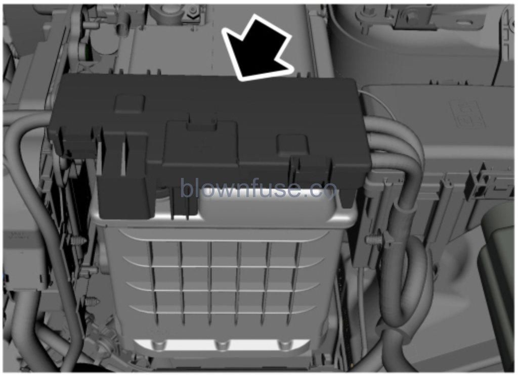
Battery Fuse Box Location


Battery Fuse Box Diagram
| Fuse | Fuse amp rating | Protected components |
|---|---|---|
| 1 | 250A | Engine compartment fuse box. |
| 2 | 60A | Electric power assist steering. |
| 3 | 100A | Body control module. |
| 4 | 70A | Heating control unit. |
| 5 | 275A | Starter. |
Engine Compartment Fuse Box Location
Engine Compartment Fuse Box Diagram
| Fuse | Fuse amp rating | Protected components |
|---|---|---|
| 1 | 60A | Engine cooling fan relay 2. |
| 2 | 50A | Engine cooling fan relay 1. |
| 3 | 40A | DC / AC inverter. |
| 4 | 40A | ABS with Eletronic Stability Program (valves). |
| 5 | 30A | Driver power seat. |
| 6 | 40A | Front blower motor. |
| 7 | 10A | Brake on/off Switch. |
| 8 | 20A | Moonroof. |
| 9 | 15A | Rear washer. Wiper. |
| 10 | 7.5A | A/C clutch relay. |
| 11 | 5A | Power point relay. Horn relay. Fuel pump relay. |
| 14 | 10A | Heated exterior mirrors. |
| 15 | 5A | Rain sensor relay. Rear washer relay. |
| 16 | 10A | Rear window wiper motor. |
| 17 | 20A | Power point 1 (or cigar lighter). |
| 18 | 20A | Power point 2. |
| 19 | – | Not used. |
| 20 | 20A | Powertrain control module. |
| 21 | 15A | Oxygen sensor heater. Catalyst monitor sensor. Canister purge valve. Variable camshaft timing solenoid valves. Vapor blocking valve. |
| 22 | 10A | A/C clutch control. Fan control – on/off. Puller fan coil (1.0 L). Coolant pump control. Run / on water pump. Exhaust gas recirculation baypass solenoid. Variable oil pump control. Variable A/C compressor valve. All-wheel drive relay module (2.0 L). Active grille shutter. |
| 23 | 15A 20A | For ignition coils (2.0 L). For ignition coils (1.0 L). |
| 24 | – | Not used. |
| 25 | 15A | Subwoofer amplifier. |
| 26 | 20A | Not used. |
| 27 | – | Not used. |
| 28 | 10A | Left horn. |
| 29 | 10A | Right horn. |
| 30 | 15A | Heated Steering wheel. |
| 31 | 5A | Temperature mass air flow sensor (2.0L). |
| 32 | 30A | Body control module (battery voltage). |
| 33 | 60A | ABS/eletronic stability program pump. |
| 34 | 50A | Trailer tow module. |
| 35 | 40A | Heated backlite. |
| 36 | 30A | Starter. |
| 37 | 40A | Positive temperature coefficient heater. |
| 38 | – | Not used. |
| 39 | – | Not used. |
| 40 | 25A | Heated seats (climate control module). |
| 41 | 15A | Subwoofer amplifier. |
| 42 | 7.5A | Intercooler puller fan (1.0 L). |
| 46 | 30A | Power window switch power switch times. |
| 47 | 20A | Fuel pump. |
| 48 | – | Not used. |
| 49 | 20A | Assisted direct start transmission fluid pump (stop/start) – power. |
| 55 | – | Not used. |
| 56 | 5A | Electrical power assisted system module. Powertrain control module. |
| 57 | 10A | Start / Stop – transmission fluid pump. |
| 58 | 10A | Left hand blind spot monitor module. Right hand blind spot monitor module. Rear video camera |
| 59 | 5A | ABS module. |
| 60 | 5A | Heated backlite relay. Heated windshield left relay. |
| 63 | 25A | Front wiper. |
| 64 | 30A | Body control module – run/start bus. |
| 69 | – | Not used. |
| 70 | – | Not used. |
| 74 | 10A | Heated wiper park. |
| 75 | – | Not used. |
| Relay | Circuits switched |
|---|---|
| 12 | Powertrain control module. |
| 13 | Starter. |
| 43 | Auxiliary power point. |
| 44 | Windshield wiper. |
| 45 | Front blower motor. |
| 50 | Run/start. |
| 51 | Not used. |
| 52 | Vehicle horn. |
| 53 | Not used. |
| 54 | Rear washer. |
| 61 | Heated backlite / heated mirror. |
| 62 | Engine cooling fan 2. |
| 65 | Fuel pump. |
| 66 | Not used. |
| 67 | A/C clutch. |
| 68 | Engine cooling fan 1. |
| 71 | Not used. |
| 72 | Not used. |
| 73 | Heated wiper park. |
| 76 | Positive temperature coefficient heater. |
| 77 | Puller fan (1.0 L Fox). |
| 78 | Not used. |
| 79 | Positive temperature coefficient heater. |
Passenger Compartment Fuse Box Location
This fuse box is located behind the glove box. To access the fuse box, do the following:
- Open the glove box and release the clips.
- Remove the storage compartment.
Passenger Compartment Fuse Box Diagram
| Fuse | Fuse amp rating | Protected components |
|---|---|---|
| F01 | 5A | Not used. |
| F02 | 5A | Humidity and incar temperature sensor. |
| F03 | 10A | Reverse parking aid module. |
| F04 | 10A | Ignition switch. Key in switch & solenoid. Start-Stop switch. |
| F05 | 20A | Central lock relay. Central unlock relay internal. |
| F06 | 10A | Power windows switches. Power sunroof switch & module inverter. |
| F07 | 30A | Not used. |
| F08 | 5A | Not used. |
| F09 | 5A | Brake shift interlock. Electrochromatic inside mirror. |
| F10 | 10A | Smart data link connector. |
| F11 | 5A | Telematic control unit (embedded modem). |
| F12 | – | Not used. |
| F13 | 15A | Driver unlock relay. |
| F14 | 30A | Not used. |
| F15 | 15A | Extended power module relay starter. |
| F16 | 15A | Not used. |
| F17 | 15A | SYNC. Mini electronic finish panel. |
| F18 | 7.5A | Not used. |
| F19 | 7.5A | Not used. |
| F20 | 10A | Not used. |
| F21 | 7.5A | Climate Control Head. |
| F22 | 7.5A | Steering column control module. Smart data link logic. Instrument cluster. |
| F23 | 20A | Audio control module. |
| F24 | 20A | Extended power mode module. |
| F25 | 30A | Not used. |
2021 Ford EcoSport Quick Reference Guide
Changing a Fuse
Fuses
| Callout | Fuse Type |
|---|---|
| A | Micro 2 |
| B | Micro 3 |
| C | Maxi |
| D | Mini |
| E | M Case |
| F | J Case |
| G | J Case Low Profile |
Recent Posts
VW Jetta Engine Fuse Box Diagram
Access the comprehensive 2010-2018 VW Jetta Passenger Fuse Box Diagram to troubleshoot electrical issues effectively.…
VW Jetta Passenger Fuse Box Diagram
Explore the comprehensive VW Jetta Passenger Fuse Box Diagram to troubleshoot electrical issues effectively. Understand…
2023 Ford F-150 Lightning Fuse Box Diagram
Under Hood Fuse Box Location Remove the front luggage compartment cover. Under Hood Fuse Box…
2022 Kawasaki NINJA H2 SX SE Brake Lever Adjuster Owner’s Manual
2022 Kawasaki NINJA H2 SX SE Brake Lever Adjuster Owner's Manual NOTICE Only adjust the front…
2023 Land Rover Range Rover Evoque Exiting The Vehicle Owners Manual
2023 Land Rover Range Rover Evoque Exiting The Vehicle SINGLE LOCKING WARNING Before exiting the…
2023 Land Rover Range Rover Evoque Front Seats Owners Manual
2023 Land Rover Range Rover Evoque Front Seats FRONT SEAT SAFETY Make sure to read…
