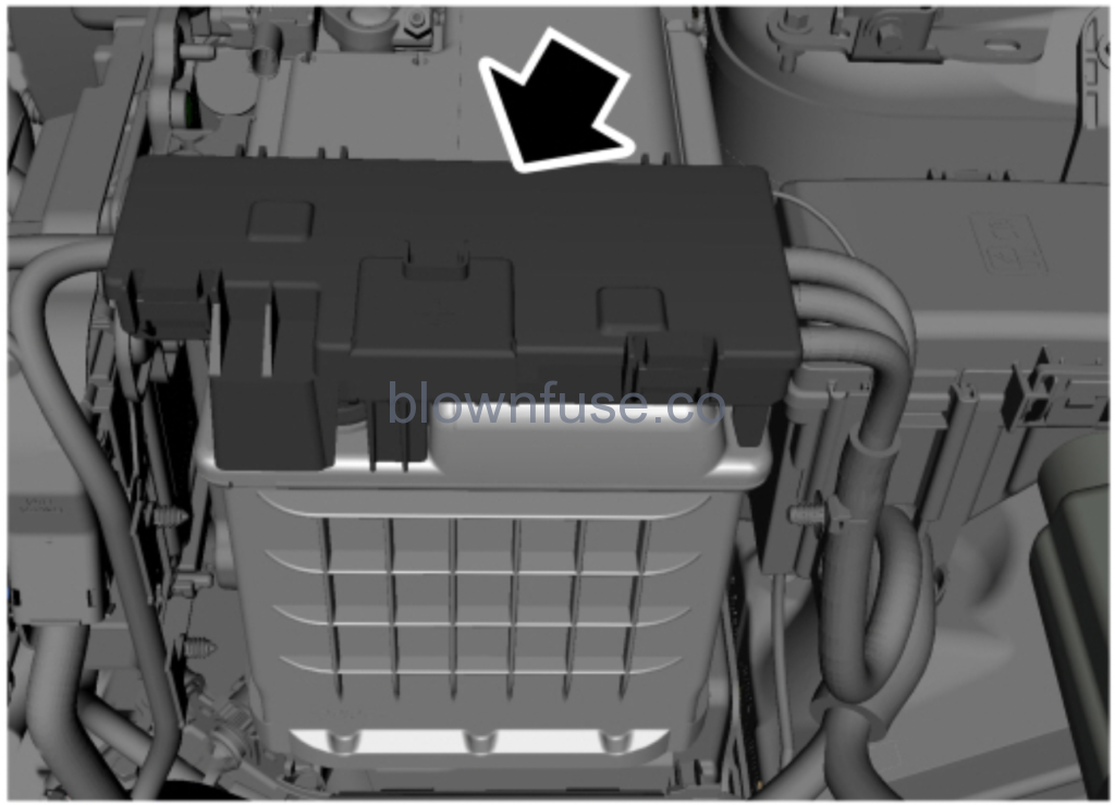
Battery Fuse Box Location This fuse box in attached to the battery positive terminal.
Battery Fuse Box Diagram Fuse Fuse amp rating Protected components 1 250A Engine compartment fuse box. 2 60A Electric power assist steering. 3 100A Body control module. 4 70A Heating control unit. 5 275A Starter.
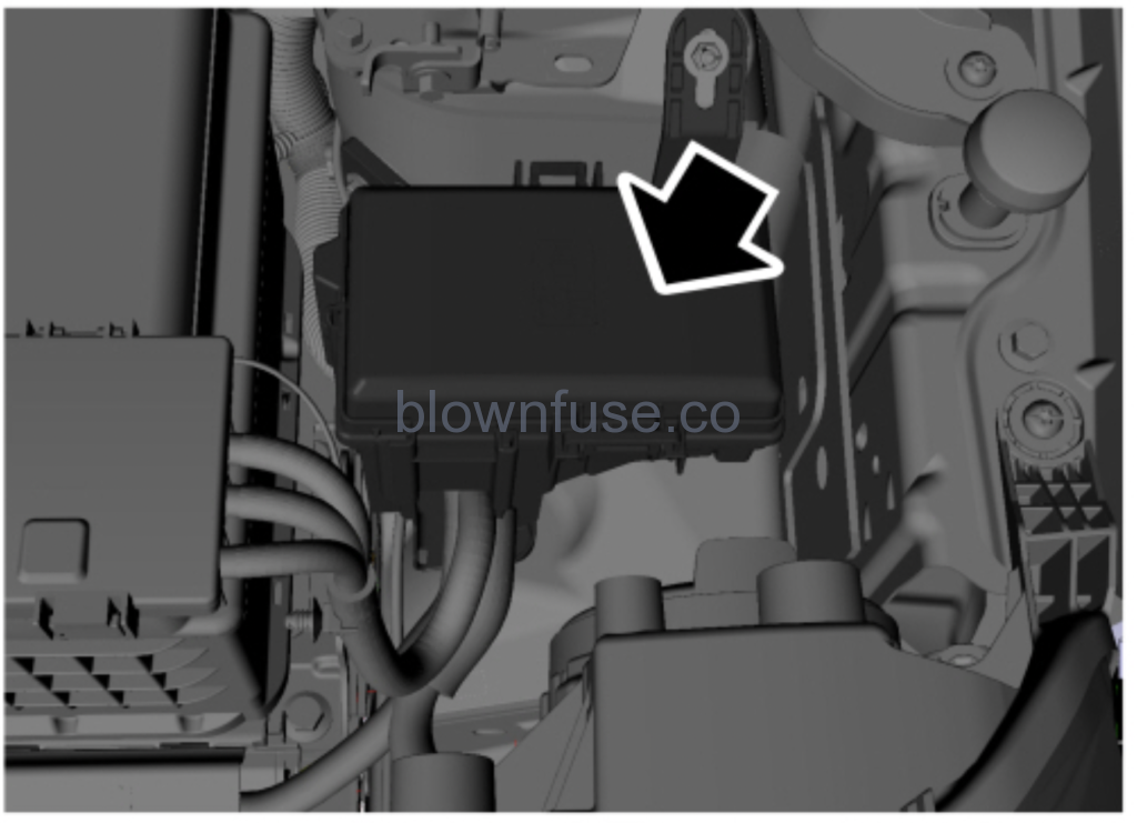
Engine Compartment Fuse Box Location This fuse box is located in the engine compartment.
Engine Compartment Fuse Box Diagram WARNING : Always disconnect the battery before servicing high current fuses.WARNING : To reduce risk of electrical shock, always replace the cover to the power distribution box before reconnecting the battery or refilling fluid reservoirs.
Your vehicle may not be equipped with all of the features listed in the fusing tables. This information describes all fusing for all available vehicle models.
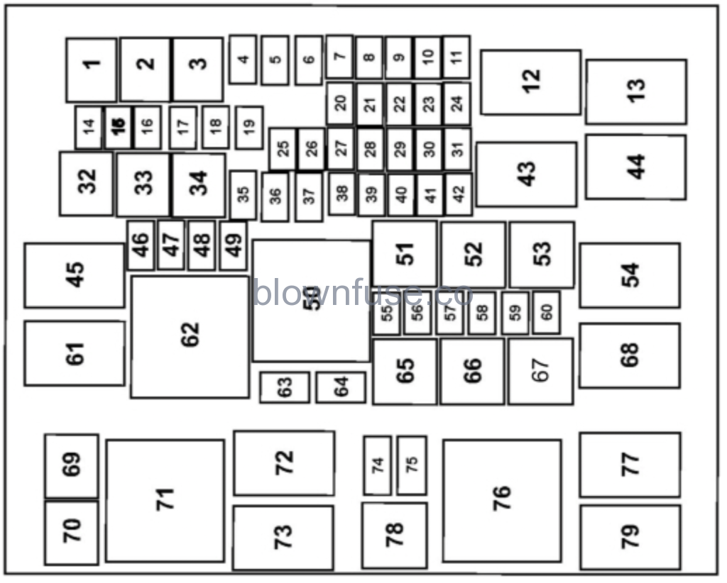
Fuse Fuse amp rating Protected components 1 60A Engine cooling fan relay 2. 2 50A Engine cooling fan relay 1. 3 40A DC / AC inverter. 4 40A ABS with Eletronic Stability Program (valves). 5 30A Driver power seat. 6 40A Front blower motor. 7 10A Brake on/off Switch. 8 20A Moonroof. 9 15A Rear washer. Wiper. 10 7.5A A/C clutch relay. 11 5A Power point relay. Horn relay. Fuel pump relay. 14 10A Heated exterior mirrors. 15 5A Rain sensor relay. Rear washer relay. 16 10A Rear window wiper motor. 17 20A Power point 1 (or cigar lighter). 18 20A Power point 2. 19 – Not used. 20 20A Powertrain control module. 21 15A Oxygen sensor heater. Catalyst monitor sensor. Canister purge valve. Variable camshaft timing solenoid valves. Vapor blocking valve. 22 10A A/C clutch control. Fan control – on/off. Puller fan coil (1.0 L). Coolant pump control. Run / on water pump. Exhaust gas recirculation baypass solenoid. Variable oil pump control. Variable A/C compressor valve. All-wheel drive relay module (2.0 L). Active grille shutter. 23 15A 20A For ignition coils (2.0 L). For ignition coils (1.0 L). 24 – Not used. 25 15A Subwoofer amplifier. 26 20A Not used. 27 – Not used. 28 10A Left horn. 29 10A Right horn. 30 15A Heated Steering wheel. 31 5A Temperature mass air flow sensor (2.0L). 32 30A Body control module (battery voltage). 33 60A ABS/eletronic stability program pump. 34 50A Trailer tow module. 35 40A Heated backlite. 36 30A Starter. 37 40A Positive temperature coefficient heater. 38 – Not used. 39 – Not used. 40 25A Heated seats (climate control module). 41 15A Subwoofer amplifier. 42 7.5A Intercooler puller fan (1.0 L). 46 30A Power window switch power switch times. 47 20A Fuel pump. 48 – Not used. 49 20A Assisted direct start transmission fluid pump (stop/start) – power. 55 – Not used. 56 5A Electrical power assisted system module. Powertrain control module. 57 10A Start / Stop – transmission fluid pump. 58 10A Left hand blind spot monitor module. Right hand blind spot monitor module. Rear video camera 59 5A ABS module. 60 5A Heated backlite relay. Heated windshield left relay. 63 25A Front wiper. 64 30A Body control module – run/start bus. 69 – Not used. 70 – Not used. 74 10A Heated wiper park. 75 – Not used.
Relay Circuits switched 12 Powertrain control module. 13 Starter. 43 Auxiliary power point. 44 Windshield wiper. 45 Front blower motor. 50 Run/start. 51 Not used. 52 Vehicle horn. 53 Not used. 54 Rear washer. 61 Heated backlite / heated mirror. 62 Engine cooling fan 2. 65 Fuel pump. 66 Not used. 67 A/C clutch. 68 Engine cooling fan 1. 71 Not used. 72 Not used. 73 Heated wiper park. 76 Positive temperature coefficient heater. 77 Puller fan (1.0 L Fox). 78 Not used. 79 Positive temperature coefficient heater.
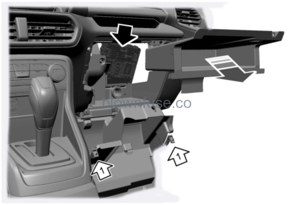
Passenger Compartment Fuse Box Location This fuse box is located behind the glove box. To access the fuse box, do the following:
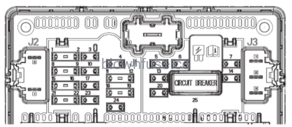
Open the glove box and release the clips. Remove the storage compartment. Passenger Compartment Fuse Box Diagram Fuse Fuse amp rating Protected components F01 5A Not used. F02 5A Humidity and incar temperature sensor. F03 10A Reverse parking aid module. F04 10A Ignition switch. Key in switch & solenoid. Start-Stop switch. F05 20A Central lock relay. Central unlock relay internal. F06 10A Power windows switches. Power sunroof switch & module inverter. F07 30A Not used. F08 5A Not used. F09 5A Brake shift interlock. Electrochromatic inside mirror. F10 10A Smart data link connector. F11 5A Telematic control unit (embedded modem). F12 – Not used. F13 15A Driver unlock relay. F14 30A Not used. F15 15A Extended power module relay starter. F16 15A Not used. F17 15A SYNC. Mini electronic finish panel. F18 7.5A Not used. F19 7.5A Not used. F20 10A Not used. F21 7.5A Climate Control Head. F22 7.5A Steering column control module. Smart data link logic. Instrument cluster. F23 20A Audio control module. F24 20A Extended power mode module. F25 30A Not used.
Battery Fuse Box
Fuse Fuse amp rating Protected components 1 250A Engine compartment fuse box. 2 60A Electric power assist steering. 3 100A Body control module. 4 70A Heating control unit. 5 275A Starter.
2019 Ford EcoSport Owners Manual
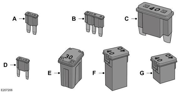
Changing a Fuse Fuses
WARNING : Always replace a fuse with one that has the specified amperage rating. Using a fuse with a higher amperage rating can cause severe wire damage and could start a fire.
Callout Fuse Type A Micro 2 B Micro 3 C Maxi D Mini E M Case F J Case G J Case Low Profile
 WARNING: Always disconnect the battery before servicing high current fuses.
 WARNING: To reduce risk of electrical shock, always replace the cover to the power distribution box before reconnecting the battery or refilling fluid reservoirs.
 WARNING: Always replace a fuse with one that has the specified amperage rating. Using a fuse with a higher amperage rating can cause severe wire damage and could start a fire.
