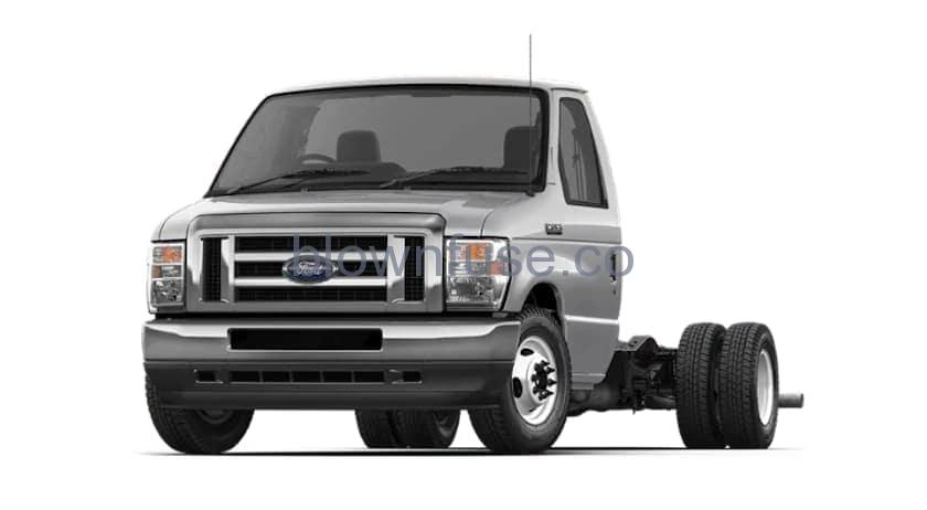
2022 Ford E-350 Fuse Box Diagram


FUSE SPECIFICATION CHART
Engine Compartment Fuse Box
    |
Note: If your vehicle has dual batteries, disconnecting the primary under hood battery does not remove power from all circuits.The engine compartment fuse box is in the engine compartment. It has high-current fuses that protect your vehicle’s main electrical systems from overloads.If you disconnect and reconnect the battery, you need to reset some features. See Changing the 12V Battery. Replace fuses with the same type and rating. See Changing a Fuse.
| Item | Rating | Protected Component |
|---|---|---|
| 1 | 20 A | Horn. |
| 2 | 50 A | Blower motor. |
| 3 | — | Not used. |
| 4 | 30 A | Starter relay. |
| 5 | — | Not used. |
| 6 | 20 A | Upfitter relay 4 (cutaway). Not used (spare) (stripped chassis). |
| 8 | — | Not used. |
| 10 | — | Not used. |
| 12 | 20 A | Power point 4. |
| 13 | 10 A | Yaw sensor (stripped chassis). Not used (spare) (cutaway). |
| 14 | 10 A | Forward looking radar (cutaway). Not used (spare) (stripped chassis). |
| 15 | — | Not used. |
| 16 | — | Not used. |
| 17 | 10 A | Powertrain control module run/start feed. |
| 18 | 10 A | Anti-lock brake system run/start feed. |
| 19 | — | Not used. |
| 20 | 30 A | Wiper power. |
| 21 | — | Not used. |
| 22 | 10 A | Wiper module (stripped chassis). Not used (spare) (cutaway). |
| 23 | — | Not used. |
| 24 | 40 A | Body control module – run power in feed 2. |
| 25 | 50 A | Body control module – run power in feed 1. |
| 26 | — | Not used. |
| 27 | 20 A | Body builder frame connector. |
| 28 | — | Not used. |
| 29 | 10 A | B+ power 12 V(special order vehicle). |
| 30 | 30 A | Power driver seat (cutaway). Not used (spare) (stripped chassis). |
| 31 | — | Not used. |
| 32 | 20 A | Vehicle power 1. |
| 33 | 20 A | Vehicle power 2. |
| 34 | 10 A | Vehicle power 3. |
| 35 | 20 A | Vehicle power 4. |
| 36 | — | Not used. |
| 37 | — | Not used. |
| 38 | 10 A | Washer relay (stripped chassis). Not used (spare) (cutaway). |
| 39 | — | Not used. |
| 41 | 30 A | Trailer brake control connector. |
| 43 | 30 A | Instrument panel connector (stripped chassis). Not used (spare) (cutaway). |
| 45 | — | Not used. |
| 46 | 10 A | A/C clutch. |
| 47 | 40 A | Upfitter relay 1 (cutaway). Not used (spare) (stripped chassis). |
| 48 | — | Not used. |
| 49 | 30 A | Pump electronics module. |
| 50 | 15 A | Injectors. |
| 51 | 20 A | Power point 1. |
| 52 | 50 A | Power at all times (PAAT) Aux AC Prep on B-pillar vehicle connector (cutaway). Not used (spare) (stripped chassis). |
| 53 | 30 A | Trailer tow park lamps. |
| 54 | 40 A | R/S feed on instrument panel connector. |
| 55 | 20 A | Upfitter 3 relay (cutaway). Not used (spare) (stripped chassis). |
| 56 | 20 A | Power point 2 prep B-pillar connector. |
| 58 | 5 A | USB smart charger. |
| 59 | 10 A | Park lamps 1 (special order vehicle). |
| 60 | — | Not used. |
| 61 | — | Not used. |
| 62 | — | Not used. |
| 63 | — | Not used. |
| 64 | — | Not used. |
| 65 | — | Not used. |
| 66 | — | Not used. |
| 67 | — | Not used. |
| 69 | — | Not used. |
| 70 | 40 A | Inverter. |
| 71 | 30 A | Anti-lock brake system valves. |
| 72 | 10 A | Brake on and off switch. |
| 73 | — | Not used. |
| 74 | — | Not used. |
| 75 | — | Not used. |
| 76 | 60 A | Anti-lock brake system pump. |
| 77 | 30 A | Voltage quality module power – body control module. |
| 78 | 10 A | Trailer tow stoplamps. |
| 79 | — | Not used. |
| 80 | 10 A | Trailer tow backup lamps. |
| 81 | — | Not used. |
| 82 | 5 A | Upfitter switch (factory location for ignition power). |
| 83 | 5 A | Upfitter switch (optional location for power at all times). |
| 84 | — | Not used. |
| 85 | — | Not used. |
| 86 | — | Not used. |
| 87 | — | Not used. |
| 88 | — | Not used. |
| 89 | — | Not used. |
| 91 | 40 A | Hot at all times (HAAT) /B+PWR on B-Pillar connector (cutaway). Battery Power on instrument panel connector(stripped chassis). |
| 93 | 10 A | Park lamps 3 (special order vehicle). |
| 94 | 10 A | Park lamps 2 (special order vehicle). |
| 95 | 20 A | Stoplamp relay. |
| 96 | — | Not used. |
| 97 | 50 A | Battery Power on Engine. B-pillar vehicle connector. Instrument panel. |
| 98 | 30 A | Trailer tow battery charge. |
| 99 | 40 A | Upfitter 2 relay (cutaway). Not used (spare) (stripped chassis). |
| 100 | — | Not used. |
| 101 | — | Not used. |
| 102 | — | Not used. |
| 103 | — | Not used. |
| 104 | — | Not used. |
| 105 | 15 A | Trailer tow right-hand and left-hand stoplamp and direction indicator relay power. |
Note: Spare fuse amperage may vary.Passenger Compartment Fuse Box
Note: If your vehicle has dual batteries, disconnecting the primary under hood battery does not remove power from all circuits.The fuse panel is to the left-hand side of the brake pedal and mounted onto the lower left-hand cowl panel. Remove the fuse panel cover to access the fuses.To remove a fuse, use the fuse puller tool provided on the inside of the fuse panel cover.Replace fuses with the same type and rating. See Changing a Fuse.
| Item | Rating | Protected Component |
|---|---|---|
| 1 | — | Not used. |
| 2 | 10 A | Left-hand front and right-hand front door lock switch (cutaway). Inverter (cutaway). Connector (stripped chassis). |
| 3 | 7.5 A | Power mirror switch (cutaway). |
| — | Not used (stripped chassis). | |
| 4 | 20 A | Not used (spare). |
| 5 | 20 A | Not used (spare). |
| 6 | 10 A | Not used (spare). |
| 7 | 10 A | Not used (spare). |
| 8 | 5 A | Not used (spare). |
| 9 | 5 A | Not used (spare). |
| 10 | — | Not used. |
| 11 | — | Not used. |
| 12 | 7.5 A | Smart datalink connector. |
| 13 | 7.5 A | Cluster. Steering column control module. |
| 14 | 15 A | Not used (spare). |
| 15 | 15 A | Not used (spare). |
| 16 | — | Not used. |
| 17 | 7.5 A | Not used. |
| 18 | 7.5 A | R/S feed for Front blend actuator/climate mode switch (cutaway). R/S feed to strip chassis connector (stripped chassis). |
| 19 | 5 A | Radio transceiver module and telematics control unit. Telematics control unit. |
| 20 | 5 A | Ignition switch. |
| 21 | 5 A | Not used. |
| 22 | 5 A | Body builder B-pillar connector (cutaway). |
| 5 A | Not used (stripped chassis). | |
| 23 | 30 A | Not used (spare). |
| 24 | 30 A | Not used (spare). |
| 25 | 20 A | Not used (spare). |
| 26 | 30 A | Not used (spare). |
| 27 | 30 A | Not used (spare). |
| 28 | 30 A | Not used (spare). |
| 29 | 15 A | Upfitter interface module (cutaway). |
| — | Not used (stripped chassis). | |
| 30 | 5 A | Not used (spare). |
| 31 | 10 A | Smart datalink connector. |
| 32 | 20 A | Radio (cutaway). |
| 33 | — | Not used. |
| 34 | 30 A | Not used (spare). |
| 35 | 5 A | Tow haul switch. |
| 36 | 15 A | Rear view mirror (cutaway). Camera lane departure (cutaway). |
| — | Not used (stripped chassis). | |
| 37 | 20 A | Not used (spare). |
| 38 | 30 A | Power window switches and motors (cutaway). |
| — | Not used (stripped chassis). |
Note: Spare fuse amperage may vary.
CHANGING A FUSE
Fuses
If electrical components in the vehicle are not working, a fuse may have blown. Blown fuses are identified by a broken wire within the fuse. Check the appropriate fuses before replacing any electrical components.
Fuse Types
| A B C D E F G H |
To dowwnload the complete user manual, please download the following file:
Recent Posts
VW Jetta Engine Fuse Box Diagram
Access the comprehensive 2010-2018 VW Jetta Passenger Fuse Box Diagram to troubleshoot electrical issues effectively.…
VW Jetta Passenger Fuse Box Diagram
Explore the comprehensive VW Jetta Passenger Fuse Box Diagram to troubleshoot electrical issues effectively. Understand…
2023 Ford F-150 Lightning Fuse Box Diagram
Under Hood Fuse Box Location Remove the front luggage compartment cover. Under Hood Fuse Box…
2022 Kawasaki NINJA H2 SX SE Brake Lever Adjuster Owner’s Manual
2022 Kawasaki NINJA H2 SX SE Brake Lever Adjuster Owner's Manual NOTICE Only adjust the front…
2023 Land Rover Range Rover Evoque Exiting The Vehicle Owners Manual
2023 Land Rover Range Rover Evoque Exiting The Vehicle SINGLE LOCKING WARNING Before exiting the…
2023 Land Rover Range Rover Evoque Front Seats Owners Manual
2023 Land Rover Range Rover Evoque Front Seats FRONT SEAT SAFETY Make sure to read…
