2022 Ford Bronco Owners Manual
FUSE BOX LOCATIONS
Engine Compartment Fuse Box
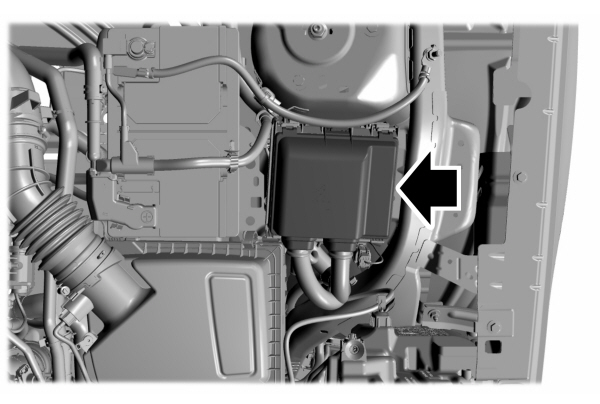
Remove the engine compartment fuse box to access the fuses. See Changing a Fuse. Passenger Compartment Fuse BoxThe fuse box is below the glove compartment.
FUSE SPECIFICATION CHART
Engine Compartment Fuse Box
 WARNING: Always disconnect the battery before servicing high current fuses. WARNING: Always disconnect the battery before servicing high current fuses. WARNING: To reduce risk of electrical shock, always replace the cover to the power distribution box before reconnecting the battery or refilling fluid reservoirs. WARNING: To reduce risk of electrical shock, always replace the cover to the power distribution box before reconnecting the battery or refilling fluid reservoirs. |
The engine compartment fuse box is in the engine compartment. It has high-current fuses that protect your vehicle’s main electrical systems from overloads.When you disconnect and reconnect the battery, you need to reset some features. See Changing the 12V Battery. Lift the release lever at the rear of the cover to remove it.

| Item | Rating | Protected Component |
|---|---|---|
| 1 | 30 A | Aftermarket auxiliary lighting. |
| 2 | — | Not used. |
| 3 | — | Not used. |
| 4 | 60 A | Supplemental heater. |
| 5 | 40 A | Supplemental heater. |
| 6 | 40 A | Supplemental heater. |
| 7 | 20 A | Heated wiper park. |
| 8 | — | Not used. |
| 9 | 60 A | Power inverter. |
| 10 | 30 A | Starter motor. |
| 11 | 15 A | Powertrain control module. |
| 12 | 15 A | Powertrain control module. |
| 13 | 15 A | Powertrain control module. |
| 14 | 15 A | Powertrain control module. |
| 15 | — | Not used. |
| 16 | — | Not used. |
| 17 | — | Not used. |
| 18 | 10 A | Powertrain control module. |
| 19 | 10 A | Anti-lock brake system module. |
| 20 | 10 A | Data link connector. |
| 21 | 5 A | Headlamp switch. |
| 22 | 20 A | Amplifier. |
| 23 | — | Not used. |
| 24 | — | Not used. |
| 25 | 25 A | Left-hand enhanced headlamps. |
| 26 | 25 A | Right-hand enhanced headlamps. |
| 27 | — | Not used. |
| 28 | — | Not used. |
| 29 | — | Not used. |
| 30 | — | Not used. |
| 31 | 5 A | Electronic power assist steering. |
| 32 | 30 A | Body control module. |
| 33 | 10 A | Front parking aid camera. Rear view camera. Blind spot information system. Gear shift actuator. |
| 34 | — | Not used. |
| 35 | 15 A | Heated steering wheel. |
| 36 | — | Not used. |
| 37 | 20 A | Horn. |
| 38 | 40 A | Blower motor. |
| 39 | — | Not used. |
| 40 | 10 A | Brake on-off switch. |
| 41 | 20 A | Amplifier. |
| 42 | 30 A | Driver power seat. |
| 43 | 40 A | Anti-lock brake system valves. |
| 44 | 40 A | Trailer tow module. |
| 45 | 30 A | Passenger power seat. |
| 46 | — | Not used. |
| 47 | 20 A | Heated seats. |
| 48 | — | Not used. |
| 49 | 60 A | Anti-lock brake system pump. |
| 50 | 60 A | Cooling fan. |
| 51 | 30 A | Moonroof. |
| 52 | 5 A | USB smart charger. |
| 53 | — | Not used. |
| 54 | — | Not used. |
| 55 | — | Not used. |
| 56 | 10 A | A/C clutch. |
| 57 | 5 A | Flood light. |
| 58 | — | Not used. |
| 59 | 40 A | Body control module. |
| 60 | 5 A | USB smart charger. |
| 61 | 20 A | Auxiliary power point. |
| 62 | — | Not used. |
| 63 | — | Not used. |
| 64 | — | Not used. |
| 65 | — | Not used. |
| 66 | — | Not used. |
| 67 | — | Not used. |
| 68 | — | Not used. |
| 69 | 15 A | Port fuel injectors. |
| 70 | 20 A | Auxiliary power point. |
| 71 | 20 A | Auxiliary power point. |
| 72 | 20 A | Rear window wiper. |
| 73 | — | Not used. |
| 74 | 30 A | Windshield wiper motor. |
| 75 | 10 A | Heated exterior mirrors. |
| 76 | 30 A | Heated rear window. |
| 77 | — | Not used. |
| 78 | 15 A | Liftgate window release. |
| 79 | — | Not used. |
| 80 | 20 A | Fuel pump. |
| 81 | 10 A | Rear window washer pump. |
| 82 | 40 A | Power inverter. |
| 83 | — | Not used. |
| 84 | 40 A | Driveline control module. |
| 85 | 5 A | Rain sensor. |
| 86 | — | Not used. |
| 87 | — | Not used. |
| 88 | — | Not used. |
Note: Spare fuse amperage may vary.
Passenger Compartment Fuse Box
The fuse box is below the glove compartment.
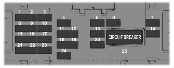
| Item | Rating | Protected Component |
|---|---|---|
| 1 | 5 A | Not used. |
| 2 | 5 A | Not used. |
| 3 | 10 A | Not used. |
| 4 | 10 A | Ignition switch. Steering column lock. |
| 5 | 20 A | Lock. Unlock. |
| 6 | 10 A | DC-AC inverter. |
| 7 | 30 A | Passenger door module. |
| 8 | 5 A | Parking assist control module. |
| 9 | 5 A | Auto-dimming interior mirror. Lane keeping system. Passenger airbag deactivation indicator. |
| 10 | 10 A | Extended power module. |
| 11 | 5 A | Telematics control unit module. |
| 12 | 5 A | Keyless keypad switch. |
| 13 | 15 A | Driver door unlock. |
| 14 | 30 A | Driver door module. |
| 15 | 15 A | Not used (spare). |
| 16 | 15 A | Not used (spare). |
| 17 | 15 A | SYNC. Receiver transceiver module. Integrated control panel. |
| 18 | 7.5 A | Wireless accessory charging module. All terrain control module. |
| 19 | 7.5 A | Not used (spare). |
| 20 | 10 A | Not used (spare). |
| 21 | 7.5 A | Not used (spare). |
| 22 | 7.5 A | Not used (spare). |
| 23 | 20 A | Not used (spare). |
| 24 | 20 A | Not used (spare). |
| 25 | 30 A | Not used (spare). |
Note: Spare fuse amperage may vary.
CHANGING A FUSE
General Information

If electrical components in the vehicle are not working, a fuse may have blown. Blown fuses are identified by a broken wire within the fuse.Engine Compartment Fuse Box
 WARNING: Always replace a fuse with one that has the specified amperage rating. Using a fuse with a higher amperage rating can cause severe wire damage and could start a fire. WARNING: Always replace a fuse with one that has the specified amperage rating. Using a fuse with a higher amperage rating can cause severe wire damage and could start a fire. |
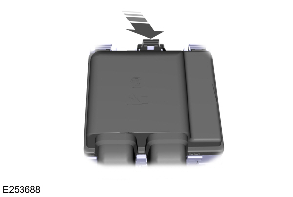
- Pull the latch toward you and remove the top cover.

- Pull the connector lever upward.
- Pull the connector upward to remove it.
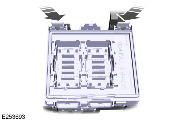
- Pull both latches toward you and remove the fuse box.
- Turn the fuse box over and open the lid.
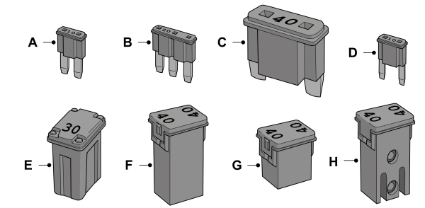
| A B C D E F G H |
To download the complete user manual, please download the following file:
