Passenger and engine fuse box diagrams for the Audi TT MK1 (8N) 1998, 1999, 2000, 2001, 2002, 2003, 2004, 2005, 2006 model year.
Passenger Fuse Box Diagram
You can see a video of the passenger fuse diagram for the Audi TT here.
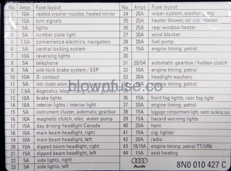
| Fuses | Amps | Circuits protected |
|---|---|---|
| 1 | 10A | Heated mirrors Heated washers |
| 2 | 10A | Direction indicators |
| 3 | 5A | Glovebox illumination Air conditioning Front fog light relay |
| 4 | 5A | Number plate light(s) |
| 5 | 7.5A | Comfort system electrics Navigation system Garage door opener |
| 6 | 5A | Central locking |
| 7 | 10A | Reversing light(s) Diagnostic connector |
| 8 | 5A | Telephone |
| 9 | 5A | ABS Electronic stability program (ESP) |
| 10 | 10A | S contact |
| 11 | 5A | Instrument panel Headlight levelling |
| 12 | 7.5A | Diagnostic connector Telephone Navigation system |
| 13 | 10A | Brake lights |
| 14 | 10A | Central locking Interior light(s) |
| 15 | 5A | Instrument panel Steering angle sensor Automatic transmission control unit |
| 16 | 10A | Cooling fan control unit |
| 17 | Not used | |
| 18 | 10A | Right main beam |
| 19 | 10A | Left main beam |
| 20 | 15A | Right dipped beam Headlight levelling |
| 21 | 15A | Left dipped beam Headlight levelling Left |
| 22 | 5A | Front right sidelight Right tail light |
| 23 | 5A | Front left sidelight Left tail light |
| 24 | 20A | Windscreen wiper(s) Windscreen washer(s) |
| 25 | 25A | Blower Air conditioning |
| 26 | 25A | Heated rear windscreen |
| 27 | 30A | Wind deflector (cabriolet) |
| 28 | 20A | Fuel pump |
| 29 | 15A | Engine management |
| 30 | Not used | |
| 31 | 5A | Haldex coupling |
| 32 | 10A | Engine management Fuel injection |
| 33 | 20A | Headlight washers (30A also used) |
| 34 | 10A | Engine management Camshaft timing solenoid |
| 35 | Not used | |
| 36 | 15A | Front fog lights Rear fog light(s) |
| 37 | 20A | Engine management |
| 38 | 15A | Central locking Immobiliser |
| 39 | 15A | Hazard warning lights |
| 40 | 20A | Horn |
| 41 | 15A | Cigarette lighter |
| 42 | 20A | Radio |
| 43 | 10A | Engine management Evaporative canister purge solenoid Heated oxygen sensor (15A also used) |
| 44 | 15A | Heated seats |
Engine Fuse Box Diagram
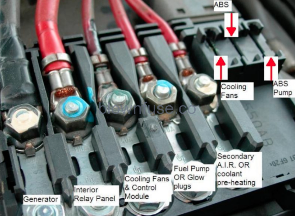
Fuse 1 – Cooling fan
Fuse 2 – ABS valves
Fuse 3 – ABS pump
Fuse FL1 – Alternator
Fuse FL2 – Interior
Fuse FL3 – Cooling fan 2
Fuse FL4 – Engine management
Fuse FL5 – Secondary air injection pump
2 thoughts on “Audi TT MK1 Fuse Box Diagram”
Mentions