Below is the engine fuse diagram for the second-generation Ford Crown Victoria (EN114), produced in 2007, 2008, 2009, 2010, and 2011. The power distribution box is located in the engine compartment. The power distribution box contains high-current fuses that protect your vehicle’s main electrical systems from overloads. Remove the panel cover to access the fuses. Inside the fuse/relay panel covers, you can find the fuse/relay label describing the fuse/relay name and capacity.
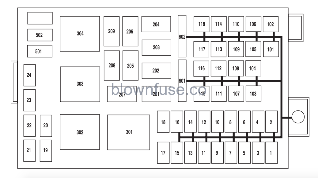
| Fuse Number | AMP Rating | Description |
|---|---|---|
| 1 | 30A | Ignition switch |
| 2 | 20A | Moon roof, Spot lights (Police vehicles only) |
| 3 | 10A | Powertrain Control Module (PCM) keep alive power, Canister vent |
| 4 | 20A | Fuel relay feed |
| 5 | 10A | Rear Air Suspension Module (RASM), VAPS module |
| 6 | 15A | Alternator regulator |
| 7 | 30A | PCM relay feed |
| 8 | 20A | Driver’s Door Module (DDM) |
| 9 | 15A | Ignition coil relay feed |
| 10 | 20A | Horn relay feed |
| 11 | 15A | A/C clutch relay feed |
| 12 | 20A or 25A | Audio (Subwoofer) (20A); Tray lamps (Police vehicles only) (25A) |
| 13 | 20A | Instrument panel power point |
| 14 | 20A | Stop lamp switch |
| 15 | 15A | Police accessory battery feed 1 (Police vehicles only) |
| 16 | 20A | Heated seats, Police accessory battery feed 2 (Police vehicles only) |
| 17 | 10A | 2007: Not used; 2008-2011: Commercial R/A |
| 18 | 10A | 2007: Not used; 2008-2011: Commercial R/A |
| 19 | 15A | Injectors |
| 20 | 15A | PCM |
| 21 | 15A | Powertrain loads and sensors |
| 22 | 20A | Police PDB outputs (Police vehicles only) |
| 23 | 20A | Police PDB outputs (Police vehicles only) |
| 24 | 10A | Heated mirrors, Rear defrost indicator |
| 101 | 40A | Blower relay feed |
| 102 | 50A | Cooling fan |
| 103 | 50A | Instrument panel (I/P) fuse box feed #1, I/P fuses 10, 12, 14, 16 and 18 |
| 104 | 50A | Instrument panel (I/P) fuse box feed #2, I/P fuses 2, 4, 6, 8, 19, 21, 23 and 25 |
| 105 | 30A | Starter relay feed |
| 106 | 40A | Anti-lock Brake System (ABS) module (Pump) |
| 107 | 40A | Rear defroster relay feed |
| 108 | 20A | Police accessory battery feed 3 (Police vehicles only), Cigar lighter (Non-police vehicles only, 2009-2011) |
| 109 | 20A | ABS module (Valves) |
| 110 | 30A | Wiper module |
| 111 | 50A | Police PDB or Police accessoiy battery feed (Police vehicles only) |
| 112 | 30A or 40A | Non-Police vehicles (30A): Air suspension compressor; Police vehicles (40A): Police PDB relay feed |
| 113 | 50A | Police light bar or Police right-hand kick panel accessory battery feed (Police vehicles only) |
| 114 | 50A | Police PDB or Police accessoiy battery feed (Police vehicles only) |
| 115 | 50A | Rear power point or Police right-hand kick panel accessory battery feed (Police vehicles only) |
| 116 | 50A | 2007-2009: Police accessory battery feed (Police vehicles only); 2010-2011: Not Used |
| 117 | 50A | 2007-2009: Police PDB or Police accessoiy battery feed (Police vehicles only); 2010-2011: Not Used |
| 118 | 50A | Rear power point or Police right-hand kick panel accessory battery feed (Police vehicles only) |
| 201 | 1/2 ISO relay | A/C clutch |
| 202 | — | Not used |
| 203 | 1/2 ISO relay | Ignition coil |
| 204 | 1/2 ISO relay | PCM |
| 205 | — | Not used |
| 206 | 1/2 ISO relay | Fuel |
| 207 | — | Not used |
| 208 | — | Not used |
| 209 | 1/2 ISO relay | Horn |
| 301 | Full ISO relay | Starter |
| 302 | Full ISO relay | Non-Police vehicles: Air compressor; Police vehicles: RUN/ACC relay |
| 303 | Full ISO relay | Blower |
| 304 | Full ISO relay | Rear defrost relay |
| 501 | Diode | 2007-2009: A/C clutch; 2010-2011: Not Used |
| 502 | Diode | PCM |
| 503 | Diode | 2007: Horn, Door latch; 2008-2011: Not used |
| 601 | 20A Circuit breaker | Power seats, Lumbar, Decklid (Police vehicles only) |
| 602 | 20A Circuit breaker | Non-Police vehicles: RUN/ACC relay (windows); Police vehicles: RUN/ACC relay feed (windows and decklid) |
1 thought on “Ford Crown Victoria Engine Fuse Diagram”
Mentions